Article Content
IEC 61869-2 Certified 11kV Current Transformer LFS-10 for Metering & Protection Applications
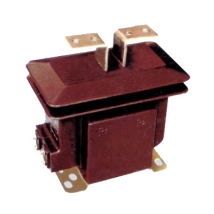
Introduction to the LFS-10 Current Transformer
The LFS-10 is a high-reliability, cast-resin insulated current transformer (CT) engineered for accurate current measurement and robust protection functions in medium-voltage power systems operating at 11kV (IEC standard) or 10kV (domestic Chinese system). Designed in strict accordance with IEC 61869-2 and GB/T 20840.2, this instrument transformer leverages advanced vacuum pressure impregnation (VPI) epoxy resin technology to deliver superior dielectric strength, environmental resilience, and long-term operational stability.
Operating Principle of Cast-Resin Insulation
Cast-resin insulation in the LFS-10 utilizes a thermosetting epoxy resin system that fully encapsulates the primary conductor, secondary windings, and magnetic core under vacuum and pressure conditions. This VPI process eliminates air voids and moisture ingress pathways, resulting in homogeneous dielectric properties and enhanced partial discharge resistance. The cured resin exhibits a dielectric constant of approximately 3.5–4.0 and volume resistivity exceeding 1×10¹⁴ Ω·cm at 20°C. Unlike oil-filled alternatives, the solid insulation provides intrinsic fire resistance (UL 94 V-0 rating), zero risk of leakage, and immunity to thermal expansion-induced mechanical stress. The resin matrix also offers excellent adhesion to copper conductors and grain-oriented electrical steel (GOES), minimizing interfacial degradation over decades of service.
Advantages Over Oil-Immersed Designs
Compared to traditional oil-immersed CTs, the LFS-10’s cast-resin construction eliminates flammability hazards, making it suitable for indoor substations, commercial buildings, and confined urban installations where fire codes prohibit combustible fluids. Maintenance requirements are drastically reduced—no oil sampling, degassing, or level checks are needed. The solid insulation maintains consistent performance across temperature cycles from –40°C to +55°C ambient, with no viscosity-related response lag during fault transients. Additionally, the compact, monolithic housing reduces footprint by up to 30% versus equivalent oil units, facilitating retrofitting into existing 11kV switchgear panels without structural modifications. Environmental compliance is assured, as the design contains no PCBs or SF6.
Typical Application Overview
The LFS-10 serves dual roles: precision metering (accuracy classes 0.2S/0.5S) and protective relaying (classes 5P10/5P20). It is commonly deployed in utility distribution substations, industrial plant switchyards, wind/solar farm collector systems, and municipal grid feeders. Its robust short-time thermal withstand capability (25 kA for 1 s) ensures survival during downstream faults, while low remanence in the GOES core enables fast reset for reclosing schemes. The transformer supports both through-type (busbar) and cable lug primary connections, accommodating conductor diameters up to 60 mm. Secondary terminals are housed in an IP54-rated enclosure with screw-type clamps rated for 6 mm² to 16 mm² copper conductors, ensuring secure, low-resistance connections for metering and relay circuits.
Technical Specifications
The LFS-10 is engineered to meet stringent electrical and environmental performance criteria essential for reliable operation in 11kV networks. All parameters comply with IEC 61869-2:2012 and GB/T 20840.2-2014, ensuring global interoperability and local regulatory acceptance.
Rated Electrical Parameters
Key electrical ratings include a highest voltage for equipment (Um) of 12 kV, corresponding to a system voltage of 11 kV (IEC) or 10 kV (GB). Standard current ratios range from 50/1 A to 3000/5 A, with multi-ratio options available via tap-changing secondary windings. Accuracy classes are defined per IEC 61869-2: for metering, 0.2S (±0.2% error at 20–120% In) and 0.5S (±0.5%); for protection, 5P10 (composite error ≤5% at 10×In) and 5P20 (≤5% at 20×In). Rated burden values are typically 5 VA, 10 VA, or 15 VA at cos φ = 0.8 lagging. The instrument security factor (FS) is ≤5 for metering cores, preventing saturation during fault currents. Short-circuit withstand is rated at 25 kA RMS for 1 second, with peak withstand current of 62.5 kA.
Insulation and Environmental Ratings
The LFS-10 features a power frequency withstand voltage of 28 kV RMS (1-minute dry test) and lightning impulse withstand of 75 kV peak (1.2/50 μs wave), per IEC 60060-1. Partial discharge levels are maintained below 10 pC at 1.2 Um/√3, verified during factory testing. The transformer operates reliably under ambient temperatures from –40°C to +55°C, relative humidity up to 100% (condensing), and altitudes ≤1000 m above sea level (derating applies above 1000 m per IEC 60071-2). The housing is UV-stabilized cycloaliphatic epoxy resin, resistant to tracking (CTI ≥600 V) and hydrolysis, suitable for both indoor and outdoor (sheltered) installations. Creepage distance exceeds 240 mm/kV for pollution degree III environments.
Mechanical and Dimensional Data
Primary conductor options include a smooth bore (Ø30–60 mm) for busbar mounting or M12/M16 threaded studs for cable lugs. Overall dimensions are 180 mm (H) × 120 mm (W) × 100 mm (D), with mounting hole pattern conforming to IEC 61869-3 Annex B. Weight is approximately 8.5 kg. Secondary terminals are arranged in a 6-pole block (for dual-core models) with labeling per IEC 61869-1 (e.g., S1/S2 for metering, K1/K2 for protection). Terminal torque specification is 1.5 N·m ±0.2 N·m to prevent conductor damage while ensuring gas-tight contact. The unit includes a dedicated grounding stud (M6) bonded to the core and housing for equipotential safety.
Typical Applications
The LFS-10’s dual functionality and rugged construction make it ideal for diverse power infrastructure scenarios requiring precise current sensing and dependable fault detection.
Substation Secondary Metering
In 11kV/0.4kV distribution substations, the LFS-10 provides revenue-grade current input to kWh meters and power quality analyzers. Its 0.2S accuracy class ensures billing compliance even at light loads (down to 1% In), critical for commercial/industrial consumers. The low phase displacement (<10 minutes at 100% In) minimizes vector error in three-phase metering systems. Installation typically involves mounting directly onto the 11kV busbar within ring-main units (RMUs) or metal-clad switchgear, with secondary leads routed to a centralized metering cabinet. The cast-resin body withstands electromagnetic interference from adjacent circuit breakers, maintaining signal integrity without shielding.
Industrial Power Distribution
Within manufacturing facilities, the LFS-10 monitors feeder currents for load management and motor protection. For example, on a 11kV motor control center (MCC) feeder supplying a 1250 kW induction motor, a 200/5 A ratio with 5P20 class provides sufficient margin for locked-rotor current (typically 6–8× full-load current) while enabling sensitive earth-fault detection via residual connection. The transformer’s high thermal withstand prevents damage during prolonged motor start-up sequences. Its compact size allows integration into space-constrained MCC lineups, and the absence of oil eliminates contamination risks in cleanroom or food-processing environments.
Renewable Energy Integration
In solar photovoltaic (PV) and wind farms, the LFS-10 interfaces between the 11kV collector grid and SCADA/protection relays. During cloud-induced irradiance fluctuations or wind gusts, rapid current variations demand low hysteresis loss in the core—achieved via high-permeability GOES laminations (losses ≤0.9 W/kg at 1.7 T, 50 Hz). The 5P10 protection class ensures correct tripping during DC-side arc faults or transformer inrush events. Outdoor-rated units are often mounted on pole-top platforms with drip shields; the hydrophobic resin surface sheds rainwater, preventing flashover during coastal salt fog conditions.
Rural and Suburban Distribution Networks
For utility-owned single-wire earth return (SWER) or three-phase overhead lines serving remote communities, the LFS-10 offers maintenance-free operation over 25+ years. Installed on pole-mounted transformers or sectionalizing switches, it feeds data to remote terminal units (RTUs) for outage management. The wide temperature tolerance accommodates desert (day/night ΔT >50°C) or alpine climates. In China’s rural grid modernization programs, the dual-standard compliance (IEC + GB) simplifies procurement and spares logistics across provincial boundaries.
Compliance with International Standards
The LFS-10’s design, testing, and certification rigorously adhere to globally recognized standards, ensuring interoperability and regulatory acceptance.
IEC 61869-2 Compliance Details
IEC 61869-2:2012 defines general requirements for instrument transformers, including accuracy definitions, insulation coordination, and type tests. The LFS-10 meets all mandatory clauses: accuracy verification per Clause 7, thermal stability per Clause 8, and short-circuit performance per Clause 9. Key compliance aspects include composite error calculation methodology for protection classes, standardized terminal marking (S1/S2), and specified limits for temperature rise (≤60 K for resin, measured by resistance method). Factory routine tests include turns ratio, polarity, and power frequency withstand, while type tests (performed annually or after design changes) cover temperature rise, short-time current, and impulse voltage.
Alignment with GB/T 20840.2
GB/T 20840.2-2014 is China’s national adoption of IEC 61869-2, with minor editorial differences but identical technical content. The LFS-10 is certified by CQC (China Quality Certification Centre) under this standard, enabling use in State Grid and China Southern Power Grid projects. Notably, GB/T 20840.2 retains the same accuracy class definitions (0.2S, 5P20) and test procedures as IEC, ensuring seamless interchangeability. Documentation (test reports, nameplates) is provided in both English and Chinese to satisfy domestic audit requirements.
Testing and Certification Requirements
Certification requires third-party validation by accredited labs (e.g., KEMA, CESI, or SGCC-approved institutes). Type test reports must demonstrate compliance with all IEC 61869-2 Clause 10 requirements, including:
- Temperature rise test: ≤60 K at 1.2×In for 8 hours
- Short-time current test: 25 kA for 1 s without deformation
- Lightning impulse test: 75 kV peak, 15 positive/negative shots
- Partial discharge test: ≤10 pC at 1.2×(12/√3) kV
Routine production tests (100% units) include visual inspection, winding resistance, ratio/polarity, and 3 kV/1 min insulation test between windings and ground. Each unit ships with a unique test certificate traceable to ISO/IEC 17025-accredited calibration.
On-Site Testing Procedures
Post-installation verification ensures the LFS-10 performs within specifications before energization. All tests follow IEC 60044-1 (withdrawn but still referenced) and IEEE C57.13.2 methodologies.
Insulation Resistance Test
Using a 2500 V DC megohmmeter, measure insulation resistance between primary-to-secondary, primary-to-ground, and secondary-to-ground. Acceptance criterion: ≥1000 MΩ at 25°C. Correct for temperature using RT2 = RT1 × 2(T1–T2)/10. Low readings indicate moisture ingress or resin cracking—requiring drying or replacement. Perform before and after high-voltage tests to detect insulation degradation.
Turns Ratio Test
Apply a low-voltage AC source (50–100 V) to the primary and measure secondary voltage. Calculate actual ratio = Vp/Vs. Compare to nameplate; tolerance is ±0.25% for metering classes, ±1% for protection. Use a dedicated ratio tester (e.g., Omicron CT Analyzer) for automated comparison. Deviations beyond tolerance suggest winding shorts or incorrect tapping.
Polarity Test
Verify reducing polarity (standard for IEC): when primary current enters P1, secondary current exits S1. Connect a 1.5 V battery between P1–P2 and a DC milliammeter between S1–S2. Momentary closure should show positive deflection. Incorrect polarity causes metering errors and relay misoperation—recheck terminal markings if failed.
Power Frequency Withstand Voltage Test
Apply 28 kV RMS (50 Hz) for 1 minute between primary and grounded secondary/housing. Monitor for flashover or excessive leakage current (>1 mA). Use a calibrated test transformer with overcurrent trip. This validates insulation integrity after transport/installation stresses. Do not perform if moisture is suspected.
Excitation (Saturation) Characteristic Test
For protection cores, plot excitation curve by applying variable voltage to secondary and measuring current. Knee-point voltage (where slope drops 45°) must exceed 1.5× rated burden voltage at 20×In. For a 5P20/15 VA CT, knee-point ≥150 V. Low knee-point indicates core saturation risk during faults—requiring core annealing or replacement.
Preventive Maintenance Guide
Although cast-resin CTs require minimal upkeep, periodic checks extend service life and prevent unexpected failures.
Annual Visual and Electrical Inspection
Inspect for surface cracks, tracking marks, or discoloration on the resin housing. Check secondary terminal tightness (torque to 1.5 N·m) and corrosion. Measure insulation resistance (≥1000 MΩ) and verify no open-circuit conditions on secondary windings—open circuits can induce dangerous overvoltages. Clean housing with non-abrasive cloth and isopropyl alcohol if contaminated with dust or salt deposits.
Five-Year Comprehensive Maintenance
Perform excitation characteristic test to detect core aging. Re-measure turns ratio and compare to baseline; drift >0.5% warrants investigation. Conduct thermal imaging during peak load to identify hot spots (>10°C above ambient at terminals suggests loose connection). Review historical fault current exposure—if cumulative I2t exceeds 80% of rated short-time capacity, consider replacement.
Maintenance Intervals and Fault Diagnosis
| Interval | Task | Acceptance Criteria |
|---|---|---|
| Annually | Visual inspection, IR test | No cracks; IR ≥1000 MΩ |
| 5 Years | Excitation test, thermal scan | Knee-point stable; ΔT ≤10°C |
| After Major Fault | Full electrical test suite | All parameters within spec |
Common faults include secondary open-circuit (causing core saturation and overheating), moisture ingress at terminal seals (evidenced by low IR), and mechanical damage from impact. Replace units showing irreversible parameter drift or physical damage—repair of cast-resin units is not feasible.
Conclusion
The LFS-10 11kV cast-resin current transformer represents a benchmark in medium-voltage instrumentation, combining IEC 61869-2 and GB/T 20840.2 compliance with field-proven reliability. Its VPI epoxy resin insulation eliminates fire and environmental hazards associated with liquid-filled designs, while the GOES silicon steel core ensures high accuracy and low losses across metering and protection applications. With a design life of 25–30 years under standard service conditions, the LFS-10 delivers exceptional total cost of ownership through minimal maintenance, compact footprint, and resilience to harsh environments—from desert substations to coastal renewable plants. Rigorous factory and on-site testing protocols guarantee performance consistency, making it a trusted choice for utilities and industrial operators worldwide. For integration into smart grid architectures, the LFS-10’s stable output characteristics support seamless interfacing with digital relays and IoT-enabled monitoring systems, future-proofing critical power infrastructure investments.