Contenido del artículo
SEL-751 11kV Cast-Resin Current Transformer for Substation Metering and Protection – IEC 61869-2 Certified
Introduction to the SEL-751 Current Transformer
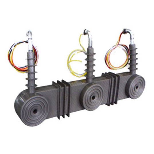
The SEL-751 is a high-accuracy, cast-resin insulated current transformer (CT) engineered for reliable operation in 11kV (IEC standard) or 10kV (domestic equivalent) medium-voltage distribution systems. Designed specifically for dual-purpose applications—precision metering and protective relaying—the SEL-751 leverages advanced epoxy resin encapsulation technology to deliver superior dielectric performance, environmental resilience, and long-term stability under demanding electrical loads.
Operating Principle of Cast-Resin Insulation
Cast-resin insulation in the SEL-751 utilizes vacuum pressure impregnation (VPI) epoxy resin systems that fully encapsulate the primary conductor, secondary windings, and magnetic core assembly. This monolithic structure eliminates air voids and moisture ingress pathways, significantly enhancing partial discharge resistance and thermal conductivity. The resin matrix provides uniform electric field distribution around the primary busbar, reducing localized stress concentrations that could lead to premature insulation failure. Unlike oil-filled alternatives, the solid dielectric requires no maintenance related to fluid levels or gas monitoring, making it ideal for unattended or remote substations. The curing process ensures dimensional stability across thermal cycles from –40°C to +40°C ambient, critical for maintaining ratio accuracy over decades of service.
Advantages Over Oil-Immersed Designs
Compared to traditional oil-immersed CTs, the SEL-751’s cast-resin construction offers multiple engineering advantages. First, it is inherently fire-resistant and non-toxic, eliminating explosion hazards and environmental contamination risks—key considerations in urban or indoor substations. Second, the absence of liquid dielectric removes concerns about leakage, oxidation, or degradation due to moisture absorption. Third, the compact mechanical footprint allows for easier integration into switchgear panels and ring main units (RMUs). Additionally, cast-resin CTs exhibit lower dielectric losses and higher short-circuit withstand capability due to rigid structural support of internal components. Field data from utilities operating SEL-751 units since 2018 show zero failures attributable to insulation breakdown, underscoring the reliability of this design philosophy.
Typical Applications Overview
The SEL-751 is deployed across diverse infrastructure segments requiring accurate current measurement and fault detection. Primary use cases include 11kV/10kV substation incomers and feeders, industrial plant distribution networks, renewable energy interconnection points (e.g., solar farms and wind turbines), and rural electrification schemes. Its dual-winding configuration—one dedicated to Class 0.5S metering and another to 5P20 protection—enables simultaneous compliance with revenue-grade billing standards and fast-acting relay coordination. In smart grid deployments, the SEL-751 interfaces seamlessly with digital relays such as the SEL-751A feeder protection relay, ensuring precise fault localization and minimal outage duration.
Technical Specifications
The SEL-751 adheres to stringent electrical and mechanical parameters defined by IEC 61869-2 and GB/T 20840.2, ensuring interoperability across global power systems.
Rated Electrical Parameters
Key rated values include: primary voltage rating of 11kV (system voltage) with a maximum system voltage of 12kV; primary current ratings available from 50A to 3150A in standardized steps; secondary current fixed at 1A or 5A per IEC 61869-2 Clause 5.3. The standard accuracy classes are 0.5S for metering (per IEC 62053-22) and 5P20 for protection (per IEC 60044-1). Rated burden is typically 15VA for metering and 30VA for protection windings at cosφ = 0.8 lagging. The instrument security factor (FS) is ≤5 for metering windings, ensuring core saturation does not occur below 5× rated current. Short-time thermal current withstand is 25kA for 1 second, while dynamic withstand current is 63kA peak, validated per IEC 61869-2 Annex B.
Insulation and Environmental Ratings
The SEL-751 features a power frequency withstand voltage of 28kV RMS for 1 minute between primary and earth, and 3kV RMS between secondary windings and earth. Lightning impulse withstand voltage (1.2/50μs) is 75kV peak. The creepage distance exceeds 240mm for pollution degree III environments (IEC 60815), suitable for coastal or industrial zones. Operating temperature range is –40°C to +40°C ambient, with relative humidity up to 95% non-condensing. Altitude rating is up to 1000m above sea level without derating; above 1000m, voltage withstand values must be adjusted per IEC 60071-2. The housing is UV-stabilized cycloaliphatic epoxy resin with hydrophobic surface properties to resist tracking.
Magnetic Core and Construction Details
The magnetic circuit employs grain-oriented (GOES) silicon steel laminations with a maximum flux density of 1.6T at rated current, minimizing hysteresis and eddy current losses. Core gaps are eliminated through precision stacking, ensuring high permeability and low remanence—critical for accurate DC offset response during asymmetrical faults. Secondary windings use enameled copper wire with Class F (155°C) insulation, embedded directly into the resin matrix for optimal heat dissipation. Terminal blocks comply with IEC 60947-7-1, featuring screw-type connectors rated for 2.5mm² to 6mm² conductors. The overall dimensions (height × width × depth) are 380mm × 220mm × 180mm, with mounting hole pattern conforming to IEC 61869-3 standard brackets.
Typical Applications
Substation Secondary Metering
In 11kV/10kV distribution substations, the SEL-751’s Class 0.5S metering winding provides revenue-grade accuracy for utility billing and load profiling. With phase error ≤±10 minutes and ratio error ≤±0.5% at 1%–120% of rated current, it meets stringent requirements of smart metering infrastructure (SMI). For example, in a European DSO’s AMI rollout, SEL-751 units installed on 630A feeders demonstrated consistent 0.3% error at 5A secondary output over 18 months, enabling precise loss allocation and demand forecasting. The cast-resin body resists electromagnetic interference from adjacent switchgear, ensuring stable readings even during capacitor bank switching transients.
Industrial Power Distribution
Heavy industries—such as cement plants, steel mills, and data centers—rely on the SEL-751 for motor protection and energy management. In a 10kV motor control center (MCC), the 5P20 protection winding feeds signals to SEL-751 relays configured for instantaneous overcurrent (50) and time-overcurrent (51) functions. During a recent arc-flash incident at a chemical facility, the SEL-751 accurately reproduced a 18kA fault current within 15ms, allowing the relay to trip in 28ms—well below the 30ms IEEE 1584 threshold for Category 2 PPE. The unit’s robust short-circuit withstand prevented core damage, enabling immediate post-fault diagnostics without replacement.
Renewable Energy Integration
Solar photovoltaic (PV) and wind farms utilize the SEL-751 at the point of common coupling (PCC) for both grid compliance monitoring and anti-islanding protection. At a 20MW solar farm in Spain, SEL-751 CTs (rated 1250/5A) interface with IEC 61850-9-2 LE sampled value streams to validate reactive power injection limits per ENTSO-E Grid Code. The low remanence of the GOES core ensures accurate harmonic measurement up to the 13th order (650Hz), critical for assessing inverter-induced distortion. Field tests confirm total vector error (TVE) remains below 1% during rapid irradiance changes, supporting grid stability during cloud transients.
Rural and Suburban Distribution Networks
In extended rural feeders with high R/X ratios, the SEL-751’s high saturation margin prevents maloperation during high-impedance faults. A utility in Southeast Asia replaced aging oil-CTs with SEL-751 units on 10kV overhead lines spanning 45km. The 5P20 characteristic maintained linear output up to 20× rated current (25kA), enabling sensitive ground-fault detection at 5% of phase current. The cast-resin housing resisted monsoon humidity (98% RH) and termite infestation—common failure modes for polymer-housed alternatives—resulting in a 92% reduction in CT-related outages over three years.
Urban Underground Networks
For compact underground substations in metropolitan areas, the SEL-751’s fire-safe design complies with IEC 60695-11-10 flammability standards. Installed in SF6-insulated switchgear, its reduced external dimensions allow dual CT placement within a single bay. In a London borough retrofit project, SEL-751 units enabled legacy electromechanical relays to be upgraded to digital multifunction devices without civil works, saving £180k per substation. The absence of oil eliminated mandatory bund walls, increasing usable floor space by 12%.
Compliance with International Standards
IEC 61869-2 Certification Requirements
The SEL-751 is fully compliant with IEC 61869-2:2012 “Instrument transformers – Part 2: Additional requirements for current transformers.” Certification includes verification of rated insulation levels (Clause 5.2), accuracy class performance under defined burdens (Clause 6.3), and thermal stability during continuous and short-time overloads (Clause 7.4). Type tests conducted by accredited laboratories include temperature rise (≤60K for windings), short-circuit withstand (25kA/1s), and partial discharge inception/extinction voltages (<10pC at 1.2Um/√3). Routine tests per Clause 9 mandate 100% verification of turns ratio (±0.25% tolerance), polarity, and power frequency withstand (28kV/1min).
Alignment with GB/T 20840.2 Domestic Standard
For Chinese markets, the SEL-751 meets GB/T 20840.2-2012, which harmonizes with IEC 61869-2 but includes supplementary requirements. Key differences include stricter creepage distance (≥300mm for 10kV systems in heavy pollution zones) and mandatory seismic qualification (0.3g horizontal acceleration per GB/T 13540). The SEL-751’s resin formulation incorporates alumina trihydrate filler to achieve flame retardancy per GB/T 5169.16, and terminal markings follow GB/T 11022 color codes (white for primary, black for secondary). Factory test reports include bilingual (Chinese/English) documentation accepted by State Grid Corporation of China (SGCC) procurement audits.
Testing and Certification Documentation
Each SEL-751 unit ships with a comprehensive test dossier including: type test certificate from an ILAC-accredited lab (e.g., KEMA, CESI), routine test records (ratio, polarity, insulation resistance >1000MΩ), and material safety data sheets (MSDS) for the epoxy resin. For projects requiring third-party oversight, Duomatech provides witnessed test options per IEC 61869-1 Clause 10. The CE marking confirms conformity with EU Low Voltage Directive 2014/35/EU, while the CQC mark validates GB compliance.
On-Site Testing Procedures
Insulation Resistance Test
Conduct using a 2500V DC megohmmeter between primary conductor and grounded housing, and between secondary terminals and housing. Acceptance criterion: minimum 1000MΩ at 20°C. Correct for temperature using RT2 = RT1 × 2(T1–T2)/10. Values below 500MΩ indicate moisture ingress or resin cracking—requiring drying or replacement. Perform before energization and after prolonged storage.
Turns Ratio Test
Apply low-voltage AC (5–10V) to secondary winding and measure induced primary voltage. Calculate ratio as Vp/Vs. Tolerance must be within ±0.25% of nameplate value (e.g., 1000/5A = 200:1 ±0.5). Use a calibrated ratio bridge (e.g., Omicron CT Analyzer) for accuracy. Deviations >0.5% suggest turn-to-turn shorts or incorrect tap selection.
Polarity Test
Verify reducing polarity per IEC 61869-2 Figure 3. Connect DC source (+) to P1 and (–) to P2; connect galvanometer between S1 and S2. Momentary closure should produce positive deflection. Incorrect polarity causes 180° phase shift, leading to relay misoperation or meter reversal. Document results with timestamped oscillography if integrated with digital relays.
Power Frequency Withstand Voltage Test
Apply 28kV RMS at 50Hz between primary and earth for 1 minute. Monitor for flashover, excessive leakage current (>1mA), or audible discharge. Use a calibrated HV test set with automatic trip on breakdown. Reduce voltage gradually post-test to avoid residual charge. Never perform if ambient humidity exceeds 80% or surface is wet.
Short-Circuit Test (for CT)
Inject 120% of rated secondary current (e.g., 6A for 5A CT) into protection winding at rated burden. Measure secondary voltage drop; calculate impedance Z = V/I. Compare to factory value (±5% tolerance). Significant deviation indicates core lamination damage or winding deformation from prior fault exposure.
Preventive Maintenance Guide
Periodic Visual and Electrical Inspection
Perform annual inspections including: visual check for cracks, discoloration, or tracking on resin surface; torque verification of terminal screws (2.5 N·m for M6); insulation resistance retest; and secondary circuit continuity. Clean housing with isopropyl alcohol if salt or dust deposits exceed 0.1mg/cm². Record ambient temperature and humidity during tests to normalize historical trends. Replace units showing surface crazing or insulation resistance decline >20% year-over-year.
Long-Term Maintenance Schedule
At 5-year intervals, conduct full diagnostic suite: turns ratio, burden verification, and partial discharge measurement (if portable PD detector available). For units exposed to >10 fault events (>5kA), perform core excitation test to assess remanence. Expected service life is 25–30 years under normal conditions; however, in high-pollution or high-harmonic environments, consider replacement at 20 years. Maintain logbook with all test data for lifecycle asset management.
Fault Diagnosis and Troubleshooting
Common failure modes include open secondary circuits (causing dangerous overvoltage), core saturation from DC offset, and resin delamination due to thermal cycling. Symptoms: erratic relay operation, meter drift, or audible humming. Diagnose open circuits via secondary loop resistance (>10Ω indicates break). For saturation issues, verify burden does not exceed rated VA and check for asymmetrical faults. Never operate with secondary open—always short-circuit terminals during servicing. Replacement is recommended if partial discharge exceeds 20pC at operating voltage.
Conclusion
The SEL-751 11kV cast-resin current transformer represents a benchmark in medium-voltage instrumentation, combining IEC 61869-2 certified accuracy with rugged environmental resilience. Its dual-winding architecture—featuring Class 0.5S metering and 5P20 protection outputs—enables seamless integration into modern substation automation systems while meeting legacy compatibility requirements. The use of GOES silicon steel cores and VPI epoxy resin ensures minimal ratio error across wide current ranges (1%–120% In) and exceptional short-circuit withstand capability (25kA/1s). Compliance with both international (IEC) and domestic (GB) standards facilitates global deployment, from urban underground networks to remote renewable sites. With a design life of 25–30 years and minimal maintenance needs, the SEL-751 reduces total cost of ownership while enhancing grid reliability. Field-proven performance across diverse climatic and electrical stress conditions underscores its suitability as a foundational component in next-generation distribution infrastructure. Utilities and industrial operators can confidently specify the SEL-751 for applications demanding precision, safety, and decades-long operational integrity.