Contenido del artículo
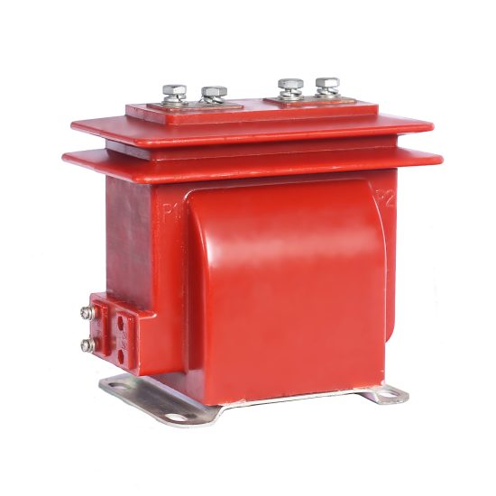
ZJC-10Q 11kV Cast-Resin Current Transformer for Substation Metering and Protection – IEC 61869-2 Certified
Introduction to the ZJC-10Q Current Transformer
The ZJC-10Q is a high-reliability, indoor/outdoor-rated cast-resin current transformer (CT) engineered for accurate current measurement and robust protection functionality in medium-voltage power systems operating at 11kV (IEC standard) or 10kV (domestic Chinese system). Designed in strict compliance with IEC 61869-2 and GB/T 20840.2, this instrument transformer leverages vacuum pressure impregnation (VPI) epoxy resin technology to encapsulate its magnetic core and windings, eliminating risks associated with oil-filled alternatives such as leakage, flammability, and environmental contamination.
Operating Principle of Cast-Resin Insulation
Cast-resin insulation in the ZJC-10Q employs a thermosetting epoxy compound that fully encapsulates the primary conductor, secondary windings, and grain-oriented electrical steel (GOES) core under vacuum and pressure. This process ensures complete void elimination, resulting in superior dielectric strength and long-term mechanical stability. The resin matrix provides uniform electric field distribution, minimizes partial discharge (typically <10 pC at 1.2 × Um/√3), and offers excellent resistance to thermal cycling, UV exposure, and chemical degradation. Unlike oil-immersed CTs, which require periodic oil sampling and tank integrity checks, the solid-dielectric design of the ZJC-10Q enables maintenance-free operation over its 25–30-year service life.
Advantages Over Oil-Immersed Designs
The ZJC-10Q eliminates fire hazards inherent in oil-filled transformers, making it suitable for indoor substations, urban switchgear rooms, and confined industrial facilities where safety regulations prohibit flammable materials. Its compact footprint—enabled by high dielectric strength of epoxy resin (≥20 kV/mm)—reduces spatial requirements by up to 30% compared to equivalent oil units. Additionally, the absence of breathing mechanisms prevents moisture ingress, ensuring stable performance in humid environments (up to 95% relative humidity). The unit’s self-extinguishing resin formulation meets IEC 60695 flammability standards, and its lightweight construction (typically 18–22 kg depending on ratio) simplifies handling and installation without cranes or specialized lifting gear.
Typical Applications Overview
Deployed across utility substations, industrial plants, and renewable energy interconnection points, the ZJC-10Q serves dual roles: precision metering (accuracy classes 0.2S or 0.5) and protective relaying (classes 5P10, 5P20, or 10P10). It is commonly installed on 11kV busbars, outgoing feeders, and transformer incomers where reliable secondary current replication is critical for revenue metering, fault detection, and load monitoring. Its robust design supports continuous operation under asymmetric short-circuit conditions up to 20 kA for 1 second, ensuring system resilience during grid disturbances.
Technical Specifications
The ZJC-10Q is engineered to meet stringent electrical and environmental performance criteria. Below is a comprehensive specification table followed by detailed subsections.
| Parameter | Value |
|---|---|
| Rated System Voltage (IEC) | 11 kV |
| Rated System Voltage (Domestic) | 10 kV |
| Primary Current (Ip) | 50 A to 3000 A (standard); custom ratios available |
| Secondary Current (Is) | 1 A or 5 A |
| Accuracy Class (Metering) | 0.2S, 0.5 |
| Accuracy Class (Protection) | 5P10, 5P20, 10P10 |
| Rated Output (VA) | 2.5, 5, 10, 15, 30 (at rated burden) |
| Short-Time Thermal Current | 20 kA for 1 s (Ith) |
| Dynamic Withstand Current | 50 kA peak (Idyn) |
| Power Frequency Withstand Voltage | 28 kV rms for 1 min (phase-to-earth) |
| Lightning Impulse Withstand Voltage | 75 kV peak (1.2/50 μs) |
| Insulation Material | VPI Epoxy Resin + GOES Core |
| Ambient Temperature Range | −25°C to +40°C |
| Maximum Altitude | 1000 m above sea level (derating required >1000 m) |
| Relative Humidity | Up to 95% non-condensing |
Electrical Performance Parameters
The ZJC-10Q maintains composite error within ±0.2% for 0.2S class under 20–120% of rated primary current, satisfying IEC 62053-22 requirements for revenue-grade metering. For protection applications, the 5P20 class guarantees ≤5% composite error at 20× rated current with specified burden, enabling precise coordination with overcurrent relays. Rated output burdens are calibrated at 50 Hz (or 60 Hz upon request), with phase displacement errors held below ±10 minutes for metering classes. The transformer’s knee-point voltage (for protection cores) exceeds 300 V, ensuring adequate saturation margin during external faults.
Environmental and Mechanical Ratings
Designed for both indoor and outdoor use, the ZJC-10Q features a UV-stabilized resin housing with IP00 rating (suitable for switchgear integration) or optional IP23 enclosure for standalone outdoor mounting. The creepage distance exceeds 25 mm/kV (medium pollution environment per IEC 60815), preventing flashovers in coastal or industrial zones. Mounting is achieved via two M12 threaded inserts or bolt-through holes compatible with standard 11kV bus support brackets. Terminal blocks accommodate 2.5–6 mm² copper conductors with screw-type clamps rated for 10 A continuous.
Typical Applications
The ZJC-10Q’s dual-certification and robust design enable deployment across diverse power infrastructure scenarios.
Substation Secondary Metering
In 11kV/0.4kV distribution substations, the ZJC-10Q provides high-fidelity current signals to kWh meters, demand recorders, and SCADA RTUs. Installed on incomer and feeder circuits, its 0.2S accuracy class ensures billing compliance even at low loads (down to 1% of Ip). For example, a 400/5 A, 0.2S unit feeding an IEC 62053-22 compliant meter delivers ±0.3% total measurement uncertainty across 4–480 A, critical for utility revenue assurance.
Industrial Power Distribution
Within manufacturing plants, data centers, and mining operations, the ZJC-10Q interfaces with multifunction power quality analyzers and motor protection relays. Its 5P20 protection winding reliably triggers circuit breakers during internal motor faults while rejecting inrush currents. In a typical 11kV motor feeder application (e.g., 800 kW induction motor), the CT’s 1000/1 A, 5P20 configuration ensures relay operation within 30 ms for phase-to-phase faults exceeding 15 kA, minimizing equipment damage.
Renewable Energy Integration
Solar PV and wind farms utilize the ZJC-10Q at the point of common coupling (PCC) for both export metering and anti-islanding protection. The transformer’s linear response up to 120% Ip accommodates variable generation profiles, while its high short-circuit withstand capability (20 kA/1s) survives grid-side faults during islanding events. In a 10 MW solar plant, dual-winding ZJC-10Q units (0.5/5P10) feed separate metering and protection circuits, complying with IEEE 1547 and local grid codes.
Rural and Suburban Distribution Networks
For overhead line reclosers and sectionalizers in rural grids, the ZJC-10Q’s compact size and weather resistance simplify pole-top installation. Operating at 10kV nominal (equivalent to 11kV IEC), it enables accurate load profiling and fault location in networks with high R/X ratios. A 600/5 A, 10P10 unit on a 15 km feeder provides sufficient secondary current (≥1 A) during end-of-line faults (as low as 800 A primary), ensuring reliable recloser tripping.
Transformer Differential Protection
When applied to 11kV/400V distribution transformers, matched sets of ZJC-10Q CTs (e.g., 400/1 A on HV side, 2000/1 A on LV side) feed differential relays. Core matching within ±2% excitation current ensures minimal through-fault spill current, preventing nuisance trips. The cast-resin design’s thermal stability avoids ratio drift during summer peak loads, maintaining protection security.
Compliance with International Standards
The ZJC-10Q is certified to IEC 61869-2:2012 (Instrument transformers – Part 2: Additional requirements for current transformers) and harmonized with China’s GB/T 20840.2-2014.
IEC 61869-2 Certification Details
Compliance encompasses type tests, routine tests, and special tests per Clause 7 of IEC 61869-2. Key verified parameters include temperature rise (<60 K for windings at 1.2× Ip), short-circuit performance (thermal and dynamic), and accuracy under harmonic distortion (tested up to 13th harmonic per IEC 61869-1 Annex D). The manufacturer provides a test report from an ISO/IEC 17025-accredited lab, including partial discharge measurements at 1.2 × Um/√3 (≤10 pC) and power frequency withstand verification at 28 kV for 60 seconds.
Alignment with GB/T 20840.2
While GB/T 20840.2 mirrors IEC 61869-2 structurally, it includes supplementary requirements for Chinese grid conditions: higher altitude derating factors (up to 3000 m), extended temperature range (−40°C to +45°C optional), and mandatory seismic testing (0.3g horizontal acceleration). The ZJC-10Q meets all GB-specific clauses, including enhanced creepage for heavy pollution (III/IV zones per DL/T 620) and stricter ratio error limits at 1% Ip for 0.2S class.
Key Differences Between IEC and Domestic Standards
Notable divergences include: (1) GB/T mandates lightning impulse testing at 85 kV for 10kV class (vs. 75 kV in IEC for 11kV); (2) GB requires 3-minute power frequency withstand (vs. 1 minute in IEC); (3) domestic standards specify minimum core cross-section for GOES material (≥25 cm² for 1000 A units). The ZJC-10Q is engineered to exceed both regimes, ensuring global deployability.
On-Site Testing Procedures
Post-installation verification ensures operational integrity. All tests follow IEC 61869-2 Annex B and IEEE C57.13.2 guidelines.
Insulation Resistance Test
Using a 2500 V DC megohmmeter, measure insulation resistance between primary-to-secondary, primary-to-ground, and secondary-to-ground. Acceptance criterion: ≥1000 MΩ at 20°C. Correct for temperature using RT = R20 × 2(20−T)/10. Values below 500 MΩ indicate moisture ingress or resin cracking, requiring replacement.
Turns Ratio Test
Apply 1–5 V AC at 50 Hz to secondary winding; measure induced primary voltage. Calculate ratio as Vp/Vs. Tolerance: ±0.25% for metering classes, ±1% for protection. Alternatively, use a dedicated ratio tester injecting 10% Ip; verify secondary current matches nominal ratio within tolerance.
Polarity Test
Connect a 1.5 V DC battery momentarily between P1 (primary input) and P2. Observe secondary voltmeter connected to S1 (positive) and S2. A positive kick confirms reducing polarity (standard for IEC). Incorrect polarity causes meter reversal or protection misoperation.
Power Frequency Withstand Voltage Test
Apply 28 kV rms (50 Hz) between primary and grounded secondary/housing for 60 seconds. Monitor for flashover or excessive leakage current (>1 mA). Use a calibrated test transformer with overcurrent trip set at 5 mA. This test validates insulation integrity after transport/installation stresses.
Excitation (Saturation) Characteristic Test
For protection windings, inject increasing AC voltage (50 Hz) into secondary while measuring current. Plot V-I curve; identify knee-point where slope decreases sharply. Verify knee-point voltage ≥ specified value (e.g., 300 V for 5P20). Low knee-point indicates core damage or incorrect burden.
Preventive Maintenance Guide
Although maintenance-free by design, periodic checks extend service life and prevent failures.
Annual Visual and Electrical Inspection
Inspect for: (1) surface cracks or tracking on resin; (2) corrosion on terminals; (3) loose mounting bolts; (4) secondary wiring integrity. Perform insulation resistance test annually. Clean housing with non-abrasive cloth and isopropyl alcohol if contaminated with salt or dust. Check grounding continuity (<0.1 Ω resistance).
Five-Year Comprehensive Maintenance
Every 60 months, conduct: (1) full ratio and polarity verification; (2) excitation curve test for protection windings; (3) thermal imaging under 50% load to detect hotspots; (4) torque check on terminal screws (2.5 N·m for M4 terminals). Replace if ratio error exceeds 150% of initial value or partial discharge exceeds 50 pC.
Maintenance Intervals and Fault Diagnosis
| Interval | Task | Fault Indicator |
|---|---|---|
| Annually | Visual inspection, IR test | Cracks, IR <500 MΩ |
| 5 Years | Ratio, polarity, excitation test | Ratio error >1%, knee-point drop >20% |
| After Fault | Full suite + thermal scan | Discoloration, abnormal noise |
Common failure modes include secondary open-circuit (causing core saturation and overheating) and moisture-induced partial discharge. Never operate with secondary open—always short-circuit before disconnecting meters/relays.
Conclusion
The ZJC-10Q 11kV cast-resin current transformer represents a benchmark in medium-voltage instrumentation, combining IEC 61869-2 and GB/T 20840.2 compliance with field-proven reliability. Its VPI epoxy resin encapsulation eliminates fire risks and environmental liabilities associated with oil-filled alternatives, while the GOES silicon steel core ensures exceptional accuracy and linearity across metering and protection ranges. Engineered for 25–30 years of maintenance-free service, the unit withstands harsh electrical stresses—including 20 kA short-circuit currents—and environmental extremes from −25°C to +40°C ambient. Applications span utility substations, industrial facilities, renewable integration points, and rural distribution networks, where its dual-winding configurations support simultaneous revenue metering and high-speed protection. Rigorous factory testing and straightforward on-site verification protocols guarantee performance consistency, while the compact, lightweight design reduces installation complexity and lifecycle costs. For engineers specifying instrumentation in 11kV (or 10kV domestic) systems, the ZJC-10Q delivers uncompromised technical fidelity, regulatory adherence, and operational longevity—making it a cornerstone component in modern, resilient power infrastructure.
Q1: Can the ZJC-10Q be used at 60 Hz systems?
A1: Yes. While optimized for 50 Hz, the ZJC-10Q operates at 60 Hz with adjusted accuracy performance. Ratio error increases by approximately 0.1% due to higher core losses; consult factory for 60 Hz calibration certificates.
Q2: What is the maximum altitude rating without derating?
A2: 1000 meters above sea level. Above this, voltage withstand values must be reduced per IEC 60071-2: Ucorrected = Urated × (1000 / H)0.125, where H is altitude in meters.
Q3: Is the secondary terminal block removable?
A3: No. Terminals are molded into the resin housing for hermetic sealing. Field modifications void warranty and compromise insulation integrity.
Q4: How does temperature affect ratio error?
A4: Ratio error drift is ≤±0.1% over −25°C to +40°C due to low thermal expansion coefficient of epoxy resin (6×10⁻⁵/°C) and stable GOES permeability.
Q5: Can multiple secondary windings be ordered?
A5: Yes. Standard configurations include dual (metering + protection) or triple windings. Specify burden and accuracy class for each winding during ordering.
Q6: What is the partial discharge inception voltage?
A6: Typically ≥18 kV (phase-to-ground) at 50 Hz, measured per IEC 60270. This exceeds the 1.2 × Um/√3 = 7.6 kV operational stress, ensuring long-term dielectric reliability.
Q7: Is seismic qualification available?
A7: Yes. Optional seismic rating per IEC 60068-2-57 (0.5g horizontal, 0.3g vertical) for installations in earthquake-prone regions. Requires reinforced core clamping and baseplate.