Contenido del artículo
Model-first: REL-10 11kV Cast-Resin Voltage Transformer for Substation Metering and Protection – IEC 61869-3 Certified
Introduction to the REL-10 Voltage Transformer
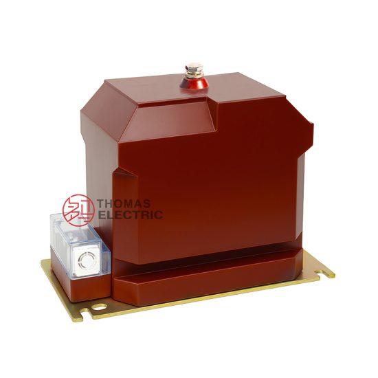
The REL-10 is a single-phase, cast-resin insulated voltage transformer (VT) engineered for high-reliability operation in 11kV (IEC nominal) or 10kV (domestic system) medium-voltage networks. Designed in strict accordance with IEC 61869-3 and GB/T 20840.3, this instrument transformer serves dual roles in both revenue-grade metering and protective relaying applications. Its robust construction leverages modern vacuum pressure impregnation (VPI) epoxy resin technology combined with grain-oriented electrical steel (GOES) cores to ensure exceptional dielectric strength, thermal stability, and long-term accuracy under varying load and environmental conditions.
Unlike traditional oil-immersed VTs, the REL-10 eliminates fire hazards, oil leakage risks, and complex maintenance protocols. The solid dielectric design provides superior resistance to partial discharge, moisture ingress, and mechanical stress—critical attributes for installations in urban substations, industrial facilities, and remote rural grids where reliability and safety are paramount.
Operating Principle of Cast-Resin Insulation
Cast-resin insulation in the REL-10 employs a two-component cycloaliphatic epoxy resin system processed under vacuum and pressure (VPI). This method ensures complete impregnation of windings and core laminations, eliminating air voids that could lead to partial discharges. The resin cures into a rigid, homogeneous structure with a dielectric constant of approximately 3.5–4.0 and volume resistivity exceeding 1×10¹⁴ Ω·cm at 20°C. The primary winding is wound directly onto the GOES core and encapsulated within multiple layers of resin, while secondary windings are precisely positioned to minimize leakage flux and phase displacement errors. This monolithic construction provides a Basic Insulation Level (BIL) of 75 kV peak for the 11kV system, satisfying IEC 61869-3 requirements for impulse withstand capability.
Advantages Over Oil-Immersed Designs
The REL-10’s dry-type, cast-resin architecture offers significant operational advantages. First, it is inherently non-flammable, making it suitable for indoor switchgear rooms without fire suppression systems—a key requirement under IEC 61439. Second, it requires no periodic oil sampling, degassing, or tank inspections, reducing lifecycle costs by up to 40% over a 25-year service life. Third, its compact footprint (typically 300 mm × 250 mm × 650 mm) enables space-constrained retrofits in existing substations. Additionally, the absence of liquid insulation eliminates environmental contamination risks during transport, installation, or end-of-life disposal. Thermal performance is enhanced through optimized resin formulation with high thermal conductivity (0.8–1.2 W/m·K), allowing continuous operation at ambient temperatures up to 40°C with a temperature rise of ≤60 K above ambient under rated load.
Typical Applications Overview
The REL-10 is deployed across diverse power infrastructure segments. In utility-owned 11kV distribution substations, it supplies accurate secondary voltages (e.g., 100/√3 V or 110/√3 V) to kWh meters and revenue billing systems. Simultaneously, its protection-class secondary winding (typically 3P or 6P accuracy) feeds overvoltage, undervoltage, and directional earth-fault relays. Industrial plants use the REL-10 for motor control center (MCC) monitoring and arc-flash mitigation schemes. Renewable integration projects—such as solar farms with 10kV collector systems—rely on its stable ratio error (<±0.2% for 0.2 class) to ensure grid-compliant power quality reporting. Its IP54-rated enclosure supports both indoor and outdoor mounting, with UV-stabilized resin formulations for prolonged exposure to sunlight and precipitation.
Technical Specifications
The REL-10 voltage transformer is defined by precise electrical and mechanical parameters aligned with international standards. Below is a comprehensive specification table followed by detailed environmental and operational constraints.
| Parameter | Value |
|---|---|
| System Voltage (IEC) | 11 kV |
| System Voltage (Domestic) | 10 kV |
| Primary Voltage (Rated) | 11 / √3 kV (phase-to-earth) |
| Secondary Voltages | Metering: 100/√3 V or 110/√3 V Protection: 100/√3 V or 110/√3 V |
| Voltage Ratio | (11000/√3) / (100/√3) = 110:1 (typical) |
| Accuracy Class (Metering) | 0.2 or 0.5 per IEC 61869-3 |
| Accuracy Class (Protection) | 3P or 6P per IEC 61869-3 |
| Rated Output (per winding) | 30 VA (metering), 50 VA (protection) |
| Insulation Level (Um) | 12 kV |
| Power Frequency Withstand Voltage | 28 kV rms, 1 min |
| Lightning Impulse Withstand Voltage | 75 kV peak (1.2/50 μs) |
| Core Material | Grain-Oriented Electrical Steel (GOES), M4 grade |
| Insulation System | VPI Cycloaliphatic Epoxy Resin, Class F (155°C) |
| Weight | Approx. 45 kg |
| Mounting | Base flange with M12 threaded inserts |
Standard Service Conditions
The REL-10 is rated for standard service conditions as defined in IEC 61869-3 Clause 5.1. Ambient temperature range is –25°C to +40°C, with a 24-hour average not exceeding +35°C. Relative humidity may reach 100% at +25°C, including temporary condensation. Installation altitude must not exceed 1000 m above sea level; for altitudes between 1000 m and 3000 m, derating factors apply per IEC 60071-2 (e.g., 1.1% reduction in withstand voltage per 100 m above 1000 m). The transformer is designed for three-phase systems with maximum continuous operating voltage of 12 kV (Um). It tolerates harmonic distortion up to 5% THD without exceeding accuracy class limits, provided total apparent power does not exceed rated output.
Electrical Performance Tolerances
Voltage ratio error for the 0.2 accuracy class must remain within ±0.2% from 25% to 100% of rated burden, and phase displacement must not exceed ±10 minutes of arc. For protection class 3P, ratio error is limited to ±3% and phase error to ±120 minutes across 25–100% burden. Burden is defined as the total impedance (resistive + reactive) connected to the secondary terminals, expressed in volt-amperes at rated secondary voltage. The REL-10 maintains these tolerances even under transient overvoltages up to 1.2×Um for 1 minute. Core losses are typically <15 W at rated voltage, contributing to low no-load current (<0.5% of rated primary current).
Typical Applications
The REL-10 voltage transformer is engineered for versatility across modern power systems, delivering precision and resilience in demanding environments.
Substation Secondary Metering
In 11kV/0.4kV distribution substations, the REL-10 provides the reference voltage for revenue metering panels. Its 0.2-class secondary winding connects to static kWh meters compliant with IEC 62053-22, ensuring billing accuracy within ±0.2%. The transformer is typically installed on the 11kV busbar, with secondary leads routed via shielded cables to the metering cubicle to minimize electromagnetic interference. For three-phase systems, three single-phase REL-10 units are connected in star configuration, enabling measurement of line-to-neutral voltages essential for tariff calculations in unbalanced loads. Utilities leverage this setup for AMI (Advanced Metering Infrastructure) integration, where real-time voltage data supports demand-side management and outage detection.
Industrial Power Distribution
Manufacturing facilities with 10kV internal distribution networks deploy the REL-10 for both energy accounting and equipment protection. In steel mills or chemical plants, where process continuity is critical, the protection-class (3P) winding feeds multifunction relays (e.g., Siemens 7SJ62) for undervoltage tripping during grid disturbances. Simultaneously, the metering winding supplies data to SCADA systems for energy efficiency audits. The cast-resin design resists chemical vapors and dust accumulation common in industrial settings, with optional silicone RTV coating enhancing hydrophobicity in humid environments. Load profiles often include nonlinear loads (e.g., VFDs), but the GOES core’s low hysteresis loss ensures minimal waveform distortion.
Renewable Energy Integration
Solar photovoltaic (PV) farms frequently operate at 10kV (domestic equivalent of 11kV IEC) on the AC side. The REL-10 monitors grid voltage at the point of interconnection (POI) to comply with grid codes such as IEEE 1547 or ENTSO-E. During cloud transients, rapid voltage fluctuations occur; the REL-10’s low leakage inductance (<50 μH) ensures fast response without overshoot. Its secondary signals feed synchrophasor measurement units (PMUs) for grid stability analysis. In wind farms with collector systems, multiple REL-10 units enable zone-selective voltage supervision for fault localization. The transformer’s immunity to DC offset (common in inverter-based resources) prevents saturation, maintaining accuracy during asymmetrical faults.
Rural and Suburban Distribution Networks
In remote areas with limited maintenance access, the REL-10’s maintenance-free design is ideal. Mounted on pole-top platforms or pad-mounted switchgear, it supports single-phase or split-phase metering for agricultural pumps and residential clusters. The 11kV rating accommodates long feeder lengths where voltage regulation is challenging; the VT’s stable ratio ensures accurate billing even at 9.5 kV or 12 kV extremes. Utilities in Southeast Asia and Africa use REL-10 units in smart grid pilots, integrating them with cellular-enabled RTUs for remote voltage monitoring. The IP54 enclosure prevents insect and rodent ingress, while UV-resistant resin prevents surface cracking after years of tropical sun exposure.
Compliance with International Standards
The REL-10 voltage transformer is certified to IEC 61869-3:2011 (“Instrument transformers – Part 3: Additional requirements for inductive voltage transformers”) and fully harmonized with China’s GB/T 20840.3-2013 standard. This dual compliance ensures global interoperability while meeting local regulatory mandates.
IEC 61869-3 Compliance Details
IEC 61869-3 defines performance, testing, and marking requirements for inductive VTs. The REL-10 meets all mandatory clauses, including accuracy class definitions (Table 2), insulation coordination (Clause 7), and temperature rise limits (Clause 8). Key tests performed during type approval include: power frequency withstand (28 kV rms for 1 min), lightning impulse (75 kV peak, 15 shots positive/negative), partial discharge (≤10 pC at 1.2×Um/√3), and temperature rise (≤60 K for windings). Markings on the nameplate include rated primary/secondary voltages, accuracy classes, burden values, polarity dots, and manufacturer identification per Clause 10. The standard also mandates short-circuit withstand capability—though VTs are inherently current-limited, the REL-10’s resin encapsulation prevents deformation under 25× rated secondary current for 1 second.
GB/T 20840.3 Alignment
GB/T 20840.3 mirrors IEC 61869-3 but includes supplementary requirements for the Chinese market. Notably, it specifies a minimum creepage distance of 240 mm/kV for outdoor pollution degree III environments—exceeding IEC’s generic guidance. The REL-10 achieves 300 mm/kV through ribbed shed design on the resin housing. Additionally, GB/T mandates factory testing of every unit (not just type tests), including ratio verification at 80%, 100%, and 120% of rated voltage. Domestic 10kV system compatibility is explicitly addressed, with test voltages adjusted to 24 kV rms (vs. IEC’s 28 kV for 11kV Um=12kV). All REL-10 units shipped to China carry CQC certification and bear the GB standard mark alongside IEC references.
Key Differences Between IEC and Domestic Standards
While IEC 61869-3 is performance-based, GB/T 20840.3 incorporates prescriptive dimensional and material rules. For example, GB/T requires GOES core thickness ≤0.30 mm (IEC allows ≤0.35 mm), reducing core loss by ~8%. Burden definition also differs slightly: IEC uses apparent power (VA) at rated secondary voltage, whereas older Chinese practices referenced impedance (Ω); however, GB/T 20840.3 now aligns with IEC on this. Environmental testing is more stringent under GB/T, requiring salt fog resistance (ASTM B117, 1000 hours) for coastal deployments. Despite these nuances, the REL-10’s design envelope satisfies both frameworks without modification, enabling seamless export and domestic use.
On-Site Testing Procedures
Post-installation verification ensures the REL-10 operates within specified tolerances. All tests should follow IEC 61869-3 Annex D and local utility protocols.
Insulation Resistance Test
Measure insulation resistance between primary winding and ground, and between secondary windings and ground, using a 2500 V DC megohmmeter. Acceptance criteria: ≥1000 MΩ at 20°C. Correct for temperature using R₂₀ = Rₜ × 1.5^((t–20)/10). Low readings indicate moisture absorption or resin cracking. Perform before and after power frequency withstand tests to detect insulation degradation. Ensure secondary terminals are shorted and grounded during primary-to-ground measurement to avoid false lows from capacitive coupling.
Turns Ratio Test
Apply a low-voltage AC source (50–100 V) to the primary and measure secondary voltage with a calibrated digital multimeter (accuracy ±0.05%). Calculate actual ratio and compare to nameplate. Tolerance: ±0.1% for 0.2-class, ±1% for 3P-class. Use a dedicated turns ratio tester (e.g., Omicron TTR300) for automated excitation and phase comparison. Test at 25%, 50%, 75%, and 100% of rated secondary voltage to verify linearity. Deviations beyond tolerance suggest winding shorts or incorrect tap selection.
Polarity Test
Verify reducing polarity per IEC 61869-3 Figure D.3. Connect a 6–12 V battery across primary terminals (H1+, H2–). Momentarily close the circuit and observe a DC voltmeter connected to secondary (X1+, X2–). A positive kick confirms correct polarity. Incorrect polarity causes 180° phase reversal, leading to metering errors or relay misoperation. Repeat three times to eliminate contact bounce artifacts. Document results with oscillograph traces if available.
Power Frequency Withstand Voltage Test
Apply 28 kV rms (for 11kV system) at 50 Hz between primary and grounded secondary/core for 1 minute. Use a calibrated test transformer with overcurrent trip set at 10 mA. No flashover or sustained discharge constitutes pass. Reduce voltage gradually post-test to avoid resonant overvoltages. This test validates insulation integrity after transport and installation stresses. Do not perform if ambient humidity exceeds 80% or if surface condensation is present.
Open-Circuit Characteristic Test
With secondary open, gradually increase primary voltage from 0 to 120% of rated (13.2 kV/√3 ≈ 7.6 kV phase). Record excitation current at 20%, 50%, 80%, 100%, and 120%. Plot Iₑ vs. Vₚ. Knee point should exceed 110% of rated voltage. Excessive current at low voltage indicates core shorted laminations; sharp knee suggests saturation risk during ferroresonance. Compare to factory baseline—deviation >15% warrants investigation.
Preventive Maintenance Guide
Although cast-resin VTs require minimal maintenance, periodic checks extend service life and prevent unexpected failures.
Periodic Inspection Protocol
Conduct annual visual and thermographic inspections. Check for: surface cracks, tracking marks, discoloration (indicating overheating), loose mounting bolts, and corroded terminals. Use an infrared camera to detect hot spots—temperature differentials >10 K between phases suggest imbalance or connection issues. Clean housing with dry cloth or low-pressure air; never use solvents that degrade resin. Verify secondary wiring tightness (torque: 2.5 N·m for M6 terminals). Inspect grounding continuity (<0.1 Ω resistance from base to substation grid).
Maintenance Intervals and Fault Diagnosis
| Interval | Action |
|---|---|
| Annually | Visual inspection, IR scan, terminal torque check |
| Every 5 Years | Insulation resistance test, ratio verification, open-circuit test |
| After Fault Events | Full suite of on-site tests (Sections 5.1–5.5) |
| End of Life (25+ years) | Dielectric spectroscopy to assess resin aging |
Common faults include: (1) Secondary open-circuit during operation—causes core saturation and overvoltage; always short secondary before disconnecting meters. (2) Moisture ingress at terminal bushings—evidenced by white powder (hydrolysis byproducts); replace affected seals. (3) Partial discharge erosion—detected via ultrasonic sensors; requires replacement if PD >20 pC persists. Never attempt field repair of resin cracks; the unit must be retired.
Conclusion
The REL-10 11kV cast-resin voltage transformer represents a benchmark in reliability, accuracy, and compliance for modern medium-voltage networks. By leveraging VPI epoxy resin insulation and GOES core technology, it delivers exceptional dielectric performance, thermal stability, and immunity to environmental stressors—outperforming legacy oil-filled designs in safety, footprint, and lifecycle cost. Its dual-winding configuration supports simultaneous metering (0.2/0.5 class) and protection (3P/6P class) functions with ratio errors well within IEC 61869-3 and GB/T 20840.3 limits across 25–100% burden ranges. Rigorous factory and on-site testing protocols ensure consistent performance, while the maintenance-free design reduces operational overhead in both urban substations and remote rural grids. With a proven service life of 25–30 years under standard conditions, the REL-10 provides a future-proof solution for utilities and industrial operators investing in resilient, standards-compliant power infrastructure. Its adaptability to renewable integration, smart grid architectures, and harsh environments underscores its role as a cornerstone component in the evolving energy landscape.