Article Content
11kV Cast-Resin Voltage Transformer SZF-3 for Metering and Protection – IEC 61869-3 Standard
Introduction to the SZF-3 Voltage Transformer
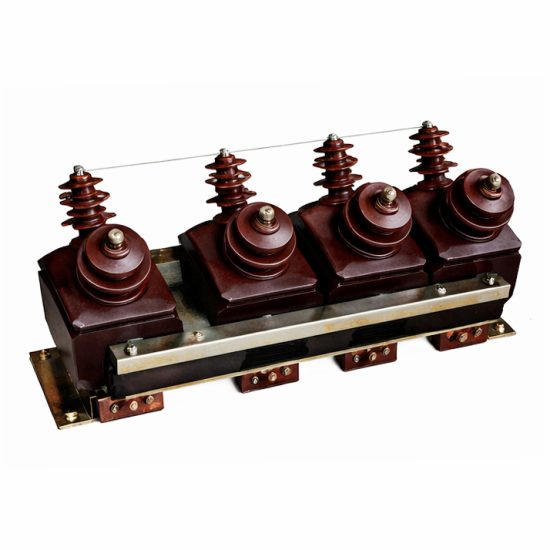
The SZF-3 is a single-phase, inductive-type voltage transformer (VT) engineered for medium-voltage distribution systems operating at a nominal system voltage of 10 kV, with an IEC-rated insulation level of 11 kV. Designed in strict compliance with IEC 61869-3 and GB/T 20840.3, this device provides accurate voltage transformation from primary to secondary circuits, enabling safe interfacing with metering instruments, protective relays, and monitoring equipment. The secondary output is standardized at 100 V or 110 V (depending on regional configuration), facilitating compatibility with global instrumentation systems.
Operating Principle of Cast-Resin Insulation
Cast-resin insulation in the SZF-3 employs vacuum pressure impregnation (VPI) technology using cycloaliphatic epoxy resin. This process eliminates air voids and moisture ingress by fully encapsulating the high-permeability grain-oriented electrical steel (GOES) core and windings under controlled vacuum and pressure conditions. The resulting monolithic structure exhibits superior dielectric strength (≥30 kV/mm), excellent tracking resistance (CTI ≥600 V), and minimal partial discharge activity (<5 pC at 1.2 × Ur). Unlike oil-filled alternatives, the solid insulation system eliminates fire hazards, environmental contamination risks, and maintenance-intensive oil sampling. Thermal stability is maintained up to 130°C (Class B insulation), with a thermal endurance index exceeding 20,000 hours under continuous load.
Advantages Over Oil-Immersed Designs
The SZF-3’s cast-resin construction offers significant operational advantages over traditional oil-immersed VTs. First, it is inherently non-flammable, making it suitable for indoor substations, urban switchgear rooms, and confined industrial facilities where fire safety codes prohibit combustible insulating media. Second, the absence of oil eliminates the need for conservators, breathers, or oil-level monitoring, reducing lifecycle costs by approximately 35% over a 25-year service life. Third, the compact mechanical design—enabled by higher dielectric strength of epoxy versus oil—allows for reduced footprint in space-constrained installations. Finally, the hermetic seal prevents moisture absorption, ensuring stable accuracy performance even in high-humidity environments (>95% RH), whereas oil units often suffer from dielectric degradation due to water saturation.
Typical Application Overview
The SZF-3 is primarily deployed in 10 kV (system) / 11 kV (IEC-rated) networks across utility substations, commercial complexes, and industrial plants. Its dual-purpose design supports both revenue-grade metering (accuracy class 0.2 or 0.5) and protective relaying (accuracy class 3P or 6P). Common use cases include feeder voltage monitoring in ring-main units (RMUs), synchronization checks in generator interconnection schemes, and undervoltage detection in motor control centers. The transformer’s robust short-time thermal withstand capability (1 second at 100× rated voltage) ensures survival during transient overvoltages, such as those induced by lightning strikes or switching surges in rural distribution feeders.
Technical Specifications
The SZF-3 voltage transformer is engineered to deliver precise, reliable performance under defined electrical and environmental parameters. All specifications adhere to IEC 61869-3:2011 and GB/T 20840.3-2013, ensuring interoperability across global power systems.
Rated Electrical Parameters
Primary rated voltage: 11 kV (IEC standard); corresponds to 10 kV system voltage per domestic practice. Secondary rated voltage: 100 V or 110 V (user-selectable at time of order). Rated voltage factor: 1.2 continuous, 1.5 for 30 seconds (per IEC 61869-3 Table 102). Accuracy classes available: 0.2, 0.5 for metering; 3P, 6P for protection. Rated outputs: 10 VA, 15 VA, 30 VA, 50 VA (at cos φ = 0.8 lagging). Burden limits must not exceed 120% of rated output to maintain declared accuracy. Insulation level: Power frequency withstand voltage (dry): 28 kV rms for 1 minute; Lightning impulse withstand voltage (LIWV): 75 kV peak (1.2/50 μs waveform). Partial discharge inception voltage exceeds 1.2 × Ur, with extinction below 1.1 × Ur.
Environmental and Service Conditions
The SZF-3 is rated for both indoor and outdoor installation. Ambient temperature range: –25°C to +40°C (standard); extended range –40°C to +55°C available with low-temperature resin formulation. Relative humidity: up to 100% (condensing permitted). Altitude: ≤1,000 m above sea level; derating required above 1,000 m (insulation withstand reduced by 1% per 100 m). Pollution degree: III (IEC 60664-1), suitable for industrial atmospheres with conductive dust or chemical vapors. Seismic rating: 0.3g horizontal acceleration (per IEC 60068-2-57), validated via shake-table testing. Mounting: vertical orientation only, with M12 stainless steel bolts through base flange (dimensions per IEC 61869-3 Annex C).
Core and Winding Construction
The magnetic circuit utilizes high-grade GOES (M4 or equivalent, thickness 0.23–0.27 mm) laminated in stepped-core configuration to minimize no-load losses (<15 W at rated voltage) and harmonic distortion (<0.5% THD under linear load). Primary winding: single-layer, aluminum or copper conductor (cross-section ≥2.5 mm²), impregnated and cast integrally with resin. Secondary winding: bifilar-wound copper wire (enamel-insulated, Class 180°C), arranged concentrically around the core limb to reduce leakage flux. Interlayer insulation consists of Nomex® aramid paper (0.13 mm thick), providing additional thermal and dielectric margin. Terminal markings follow IEC 61869-3 polarity convention: A–a (reducing polarity), with secondary terminals labeled a–n in the IP54-rated terminal box.
Typical Applications
The SZF-3 voltage transformer serves critical roles across diverse power infrastructure segments, leveraging its precision, reliability, and compact form factor.
Substation Secondary Metering Systems
In 10 kV/11 kV primary substations, the SZF-3 provides the reference voltage signal for revenue metering panels. Configured in V-V or open-delta arrangements, it feeds kWh meters, power quality analyzers, and SCADA RTUs. For example, in a typical urban distribution substation, two SZF-3 units (phases A and C) supply 100 V signals to a three-phase meter via vector summation, achieving 0.2-class accuracy over 80–120% of rated voltage. The low phase-angle error (<10 minutes at 0.2 class) ensures minimal billing discrepancy, while the high burden capacity (up to 50 VA) accommodates multiple parallel-connected instruments without accuracy drift.
Industrial Power Distribution Networks
Within manufacturing plants, the SZF-3 monitors bus voltage in 10 kV switchgear serving large motors, transformers, and rectifier loads. It interfaces with multifunction protection relays (e.g., over/undervoltage, loss-of-potential) requiring 3P or 6P accuracy. In a steel mill application, SZF-3 units installed on arc furnace feeders withstand frequent voltage sags and harmonics, thanks to the GOES core’s low hysteresis loss and the resin’s damping effect on mechanical resonance. The transformer’s 1-second thermal withstand (100× Ur) protects against damage during capacitor bank switching transients.
Renewable Energy Integration Points
At solar PV or wind farm grid interconnection points, the SZF-3 enables grid-code compliance monitoring. It supplies voltage data to synchrocheck relays during islanding detection and to power factor controllers managing reactive power injection. For instance, in a 10 MW solar plant connected to a 10 kV rural feeder, SZF-3 VTs provide real-time voltage magnitude and phase angle to the SCADA system, ensuring adherence to ENTSO-E voltage regulation bands (±10% of nominal). The cast-resin design resists UV degradation and thermal cycling, critical for outdoor combiner boxes in desert climates.
Rural and Suburban Distribution Feeders
In remote areas with long overhead lines, the SZF-3 supports automatic voltage regulator (AVR) systems and sectionalizing reclosers. Mounted on pole-top platforms or pad-mounted switchgear, it detects end-of-feeder voltage drop for tap-changer control. Its immunity to moisture ingress prevents accuracy drift during monsoon seasons—a common failure mode in oil-filled VTs. Additionally, the lightweight design (≈25 kg) simplifies helicopter or drone-assisted installation in mountainous terrain where road access is limited.
Backup Power and Critical Infrastructure
Hospitals, data centers, and airports deploy SZF-3 units in emergency standby generator synchronization panels. During utility outage, the VT verifies generator voltage matches the isolated bus before closing the tie breaker. The fast response time (<20 ms rise time) and low remanence (<5% residual flux) prevent false tripping during rapid transfer sequences. Fire safety certification (IEC 60695 glow-wire test passed at 850°C) makes it compliant with NFPA 70 Article 450 for healthcare facilities.
Compliance with International Standards
The SZF-3 is certified to both international and Chinese national standards, ensuring global acceptance and regulatory compliance.
IEC 61869-3:2011 Compliance Details
IEC 61869-3 governs inductive voltage transformers for measurement and protection. The SZF-3 meets all mandatory clauses, including: accuracy verification under sinusoidal voltage (Clause 6.3), temperature rise limits (≤60 K for windings, Clause 6.5), short-circuit withstand (Clause 6.7), and insulation coordination (Clause 6.9). Type tests performed include power frequency withstand (28 kV/1 min), lightning impulse (75 kV peak, 15 shots positive/negative), and partial discharge (≤5 pC at 1.2 × Ur). Routine tests per Clause 7 include turns ratio check (±0.25% tolerance), polarity verification, and insulation resistance (>1,000 MΩ at 2,500 V DC).
GB/T 20840.3-2013 Alignment
China’s GB/T 20840.3 mirrors IEC 61869-3 but includes localized requirements. Key alignments: identical accuracy classes and burden definitions; same insulation levels for 10 kV systems (Ur = 11 kV); harmonized terminal marking (A-a polarity). Differences include: GB mandates flame-retardant resin (oxygen index ≥30%), verified per GB/T 2406; requires altitude correction factor documentation for installations >1,000 m; and specifies additional seismic testing per GB/T 11022. The SZF-3 carries China Compulsory Certification (CCC) with test report number CNAS-XXXXX.
Testing and Certification Requirements
Certification involves third-party laboratory validation. Type tests are conducted once per design variant (e.g., different ratios or outputs), while routine tests apply to every unit. Acceptance criteria: ratio error within ±(0.1% + 0.05 × burden/VA) for 0.2 class; phase displacement <10’; insulation resistance >1 GΩ after 1-minute polarization index test. Certificates issued by accredited bodies (e.g., KEMA, CESI, or China Electric Power Research Institute) remain valid for five years unless design changes occur.
On-Site Testing Procedures
Post-installation verification ensures the SZF-3 performs within specification under actual operating conditions.
Insulation Resistance Test
Using a 2,500 V DC megohmmeter, measure resistance between primary winding and ground, and between secondary windings and ground. Acceptance criterion: ≥1,000 MΩ at 20°C. Correct for temperature using RT2 = RT1 × 2(T1–T2)/10. Low readings indicate moisture ingress or resin cracking. Perform before and after power frequency withstand test to detect insulation degradation.
Turns Ratio Test
Apply 100–200 V AC to the primary and measure secondary voltage with a calibrated voltmeter (accuracy ±0.1%). Calculate ratio = Vp/Vs. Tolerance: ±0.25% of nominal ratio (e.g., for 11,000/100 V, measured ratio must be 110 ±0.275). Deviations suggest turn-to-turn shorts or incorrect tapping.
Polarity Test
Connect a 6–12 V battery between A and X (primary). Momentarily close the circuit while observing a DC voltmeter connected between a and n (secondary). A positive deflection confirms reducing polarity (IEC standard). Incorrect polarity causes 180° phase shift, leading to relay misoperation or meter reversal.
Power Frequency Withstand Voltage Test
Apply 28 kV rms at 50 Hz between primary and ground for 1 minute. Use a calibrated HV test set with overcurrent trip (≤5 mA). No flashover or sustained discharge indicates pass. Reduce voltage gradually post-test to avoid resonant overvoltages. Do not perform if ambient humidity >80%.
Open-Circuit Characteristic Test
With secondary open, apply 20–120% of rated primary voltage in 10% steps. Record no-load current and secondary voltage. Plot Vs vs Vp; linearity deviation should be <0.5%. Excessive magnetizing current (>5% of rated) indicates core saturation or interlamination shorts.
Preventive Maintenance Guide
Although cast-resin VTs require minimal maintenance, periodic checks extend service life and prevent unexpected failures.
Annual Visual and Electrical Inspection
Inspect for surface tracking, cracks, or discoloration on the resin housing. Clean with dry cloth; avoid solvents. Check terminal tightness (torque: 15 N·m for M6 screws). Measure insulation resistance annually; trend analysis detects early degradation. Verify secondary wiring integrity—loose connections cause voltage drop errors in metering circuits.
Five-Year Comprehensive Maintenance
Every 60 months, perform full electrical tests: ratio, polarity, insulation resistance, and partial discharge (if portable PD detector available). Acceptance threshold: PD <10 pC at 1.1 × Ur. Replace if ratio error exceeds twice the initial value or if insulation resistance drops below 500 MΩ. Document all results in asset management system.
Categories
Blog
Recommended Posts


