Article Content
JDZW-35K 33kV Cast-Resin Voltage Transformer for Substation Metering and Protection – IEC 61869-3 Certified
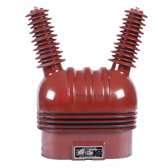
Introduction to the JDZW-35K Voltage Transformer
The JDZW-35K is a single-phase, inductive-type voltage transformer (VT) engineered for precise voltage measurement and reliable protective relay operation in medium-voltage power systems. Designed for nominal system voltages of 35 kV (domestic designation) with an IEC-standard primary voltage rating of 33 kV, this device adheres strictly to international performance and safety benchmarks. Its core construction utilizes grain-oriented electrical steel (GOES), which minimizes hysteresis and eddy current losses, ensuring high efficiency and thermal stability under continuous load conditions.
Operating Principle of Cast-Resin Insulation
The JDZW-35K employs vacuum pressure impregnation (VPI) epoxy resin technology to fully encapsulate its magnetic core and windings. This process eliminates air voids and moisture ingress pathways by saturating the entire active assembly under vacuum before curing the thermoset resin under controlled pressure. The resulting monolithic structure provides superior dielectric strength—typically exceeding 70 kV/mm—and exceptional resistance to partial discharge (PD levels < 5 pC at 1.2 × Um/√3). Unlike oil-filled alternatives, the solid insulation system is non-flammable, requires no maintenance for fluid levels or gas monitoring, and remains stable across wide temperature ranges (-40°C to +40°C ambient). The resin’s coefficient of thermal expansion closely matches that of copper and steel, preventing mechanical stress during thermal cycling—a critical factor for long-term reliability in outdoor substations subject to diurnal and seasonal variations.
Advantages Over Oil-Immersed Designs
Compared to traditional oil-immersed VTs, the JDZW-35K offers significant operational and safety benefits. First, it eliminates fire hazards associated with mineral oil, making it suitable for indoor installations near sensitive equipment or in urban substations with strict fire codes. Second, the absence of liquid insulation removes risks of leakage, environmental contamination, and the need for periodic oil sampling or degassing. Third, the compact, hermetically sealed design reduces footprint by up to 30%, facilitating retrofitting into space-constrained switchgear bays. Additionally, cast-resin units exhibit faster thermal response times and lower no-load losses (< 25 W at rated voltage), contributing to energy efficiency over a 25–30-year service life. These attributes align with modern grid requirements for low-maintenance, environmentally sustainable, and inherently safe instrumentation.
Typical Applications Overview
The JDZW-35K is primarily deployed in 35 kV distribution networks where accurate voltage transformation is essential for revenue metering, power quality monitoring, and protective relaying. Common installations include utility-owned outdoor substations, industrial plant switchyards, and renewable energy interconnection points (e.g., solar farms feeding into 35 kV collector grids). Its robust design supports both indoor and outdoor mounting, with IP23-rated terminal boxes protecting secondary connections from dust and water ingress. In smart grid deployments, the VT’s stable ratio accuracy enables integration with digital metering systems and phasor measurement units (PMUs), supporting real-time grid analytics and fault location services.
Technical Specifications
The JDZW-35K is engineered to deliver precision and durability under standard service conditions while maintaining compliance with IEC 61869-3 and GB/T 20840.3. Below are its key electrical and environmental parameters.
| Parameter | Value |
|---|---|
| Primary Voltage (Up) | 33 kV (IEC), 35 kV (system) |
| Secondary Voltage (Us) | 100/√3 V or 100 V (configurable) |
| Voltage Ratio | 33,000/√3 : 100/√3 V or 33,000 : 100 V |
| Accuracy Class | 0.2 / 0.5 / 3P (per burden) |
| Rated Output (VA) | 30 VA (Class 0.2), 50 VA (Class 0.5), 100 VA (Class 3P) |
| Insulation Level (LI/AC) | 170 kV / 70 kV (1 min) |
| Short-Time Thermal Withstand | 1.5 × In for 30 s (secondary short-circuit) |
| Frequency | 50 Hz ± 0.5 Hz |
| Ambient Temperature Range | -40°C to +40°C |
| Altitude | ≤ 1,000 m above sea level (derating required >1,000 m) |
| Relative Humidity | ≤ 95% (non-condensing) |
| Core Material | Grain-Oriented Electrical Steel (GOES), 0.3 mm thickness |
| Insulation System | VPI Epoxy Resin, UL 94 V-0 flame rating |
Standard Service Conditions
The JDZW-35K is rated for continuous operation under IEC 60060-defined standard atmospheric conditions: ambient temperature between -40°C and +40°C, relative humidity not exceeding 95% (non-condensing), and installation altitude up to 1,000 meters. At altitudes above 1,000 m, the external insulation withstand voltage must be derated by 1% per 100 m increment due to reduced air density. For example, at 2,000 m, the power frequency test voltage would be reduced from 70 kV to 63 kV. The transformer is designed for horizontal or vertical mounting on support structures with adequate seismic bracing (rated for Zone 2 per IEC 60068-2-57). Condensation-prone environments require supplementary heating elements in terminal enclosures to prevent moisture accumulation on secondary terminals.
Electrical Performance Tolerances
Voltage ratio error and phase displacement are tightly controlled per IEC 61869-3. At rated burden and 80–120% of rated voltage, the ratio error for Class 0.2 does not exceed ±0.2%, while phase displacement remains within ±10 minutes. For protection class 3P, ratio error is limited to ±3% and phase error to ±120 minutes across 5–100% of rated voltage. Burden tolerance is ±10% of declared VA rating. No-load current is typically ≤ 0.05 A at 1.2 × Un, ensuring minimal excitation losses during light-load conditions. These tolerances guarantee compatibility with modern digital relays requiring high-fidelity voltage inputs for distance protection and synchrocheck functions.
Typical Applications
The JDZW-35K serves as a foundational component in diverse medium-voltage infrastructure, enabling accurate voltage sensing for both operational and safety-critical functions.
Substation Secondary Metering
In utility-owned 35 kV distribution substations, the JDZW-35K provides the reference voltage signal for revenue-class kWh meters and power quality analyzers. Its Class 0.2 accuracy ensures billing precision within ±0.2% over the full load range (10–100% of rated current equivalent). The transformer is typically connected phase-to-ground on each of the three phases, with secondary windings wired to a common neutral point grounded at the metering panel. This configuration supports vector group measurements for detecting unbalanced loads or harmonic distortion. In smart metering deployments, the stable output enables time-synchronized data logging for demand-side management and loss allocation studies.
Industrial Power Distribution
Large manufacturing facilities often operate internal 35 kV ring-main units (RMUs) fed from the utility grid. Here, the JDZW-35K supplies voltage inputs to multifunction protection relays (e.g., SEL-351 or Siemens 7SJ) for overvoltage, undervoltage, and directional earth-fault detection. The 3P accuracy class ensures reliable operation during transient faults, where secondary voltage may drop to 5% of nominal. The cast-resin design withstands electromagnetic interference (EMI) from nearby variable-frequency drives (VFDs), maintaining signal integrity without shielding. Industrial users benefit from the VT’s immunity to oil degradation in high-temperature environments (e.g., steel mills or chemical plants).
Renewable Energy Integration
Solar photovoltaic (PV) farms frequently interconnect to the grid via 35 kV collector systems. The JDZW-35K monitors point-of-interconnection (POI) voltage for anti-islanding protection and reactive power control per IEEE 1547 or GB/T 19964 standards. During cloud transients, rapid voltage fluctuations must be accurately captured; the low leakage inductance of the GOES core ensures fast response (< 10 ms rise time). The VT’s outdoor rating (IP23) allows direct mounting on PV combiner boxes or step-up transformer pads without additional enclosures, reducing balance-of-system costs.
Rural and Suburban Distribution Networks
In remote or semi-urban areas, 35 kV lines serve as backbone feeders for rural electrification. The JDZW-35K’s maintenance-free operation is ideal for unmanned substations, where access for oil sampling or bushing cleaning is impractical. Its robust insulation withstands pollution-induced flashovers in coastal or desert regions (creepage distance ≥ 25 mm/kV). Utilities deploy these VTs for automated feeder reclosing schemes, where voltage presence detection determines successful fault clearance before re-energization.
Compliance with International Standards
The JDZW-35K is certified to both global and Chinese national standards, ensuring interoperability and regulatory acceptance across markets.
IEC 61869-3 Compliance Details
IEC 61869-3 specifies performance, testing, and marking requirements for inductive voltage transformers. The JDZW-35K meets all clauses, including:
– Clause 5.2: Accuracy verification under defined burdens and voltage ranges
– Clause 6.3: Power frequency withstand tests (70 kV for 1 min between HV-LV and HV-ground)
– Clause 7.1: Partial discharge limits (< 10 pC at 1.2 × Um/√3)
– Clause 8.4: Temperature rise tests (winding rise ≤ 55 K above ambient at rated VA)
Certification includes type tests performed by accredited laboratories (e.g., KEMA or CESI), with routine tests conducted on every unit before shipment.
GB/T 20840.3 Alignment
China’s GB/T 20840.3 mirrors IEC 61869-3 but includes localized requirements:
– Higher creepage distance for polluted environments (≥ 31 mm/kV in Class IV)
– Mandatory lightning impulse test with 1.2/50 μs waveform at 170 kV peak
– Secondary terminal labeling in Chinese characters per GB/T 11022
The JDZW-35K is dual-certified, bearing both CQC and CE marks, facilitating deployment in domestic projects and export markets.
Key Differences Between IEC and Domestic Standards
While IEC 61869-3 uses 33 kV as the standard system voltage for 35 kV-class equipment, GB/T 20840.3 references 35 kV directly. This affects test voltage calculations: IEC defines Um = 36 kV, whereas GB uses Um = 40.5 kV, resulting in slightly higher insulation requirements in Chinese standards. Additionally, GB mandates stricter short-circuit withstand capability for secondary circuits (3 s vs. IEC’s 1 s). Despite these differences, the JDZW-35K’s design envelope accommodates both, using conservative insulation margins.
On-Site Testing Procedures
Post-installation verification ensures the JDZW-35K performs within specifications before energization.
Insulation Resistance Test
Using a 2,500 V DC megohmmeter, measure insulation resistance between:
– Primary winding and ground
– Secondary winding and ground
– Primary and secondary windings
Acceptance criteria: ≥ 1,000 MΩ at 20°C. Correct for temperature using RT = R20 × 2(20−T)/10. Values below 500 MΩ indicate moisture ingress or resin cracking and require drying or replacement.
Turns Ratio Test
Apply 100–200 V AC to the primary and measure secondary voltage with a calibrated voltmeter (accuracy class 0.1). Calculate ratio error: [(Vp/Vs)measured − (Np/Ns)] / (Np/Ns) × 100%. Tolerance: ±0.2% for Class 0.2, ±0.5% for Class 0.5. Deviations beyond tolerance suggest winding shorts or incorrect tap selection.
Polarity Test
Connect a 6–12 V battery momentarily between primary terminals (H1 to H2). Observe secondary voltage polarity with a DC millivoltmeter (X1 to X2). A positive deflection confirms subtractive (reducing) polarity, standard for IEC-compliant VTs. Incorrect polarity causes 180° phase reversal, leading to metering errors or relay misoperation.
Power Frequency Withstand Voltage Test
Apply 70 kV RMS at 50 Hz for 1 minute between primary and grounded secondary/core. Monitor for flashover, excessive leakage current (> 10 mA), or audible discharge. This test validates insulation integrity after transport and installation stresses. Use a calibrated test transformer with overcurrent trip set at 100 mA.
Open-Circuit Characteristic Test
Gradually increase primary voltage from 20% to 150% of rated value while measuring secondary voltage and excitation current. Plot Vs vs. Iexc. The knee point should occur above 120% Un; premature saturation indicates core damage. At 120% Un, Iexc must not exceed 0.1 A for Class 0.2 units.
Preventive Maintenance Guide
Although cast-resin VTs require minimal maintenance, periodic checks extend service life and prevent unexpected failures.
Periodic Inspection Schedule
Conduct visual and electrical inspections annually:
– Check for surface tracking, cracks, or UV degradation on resin housing
– Verify terminal tightness (torque: 15 N·m for M8 bolts)
– Measure insulation resistance (baseline comparison)
– Inspect grounding continuity (< 0.1 Ω resistance)
After severe weather (lightning, ice storms), perform additional ratio and polarity tests.
Maintenance Intervals and Fault Diagnosis
Every 5 years, conduct a full diagnostic suite:
– Partial discharge measurement (should remain < 10 pC)
- Dielectric frequency response (DFR) to detect moisture
- Thermal imaging under load to identify hot spots
Common failure modes include:
- **Ratio drift**: Caused by turn-to-turn shorts; confirmed by open-circuit test
- **Insulation breakdown**: Indicated by low IR values and PD spikes
- **Terminal corrosion**: Leads to contact resistance rise; clean with isopropyl alcohol
Replace units exhibiting irreversible degradation; repair is not feasible due to monolithic construction.
| Interval | Activity | Acceptance Criteria |
|---|---|---|
| Annual | Visual + IR test | IR ≥ 1,000 MΩ; no physical damage |
| 5 Years | PD + DFR + Thermal scan | PD < 10 pC; tan δ < 0.5%; ΔT < 10°C |
| Post-Fault | Full electrical test suite | All parameters within spec |
Conclusion
The JDZW-35K 33kV cast-resin voltage transformer represents a technically mature solution for modern medium-voltage instrumentation needs. By leveraging VPI epoxy resin encapsulation and GOES core technology, it delivers exceptional dielectric strength, thermal stability, and long-term accuracy without the operational liabilities of oil-filled designs. Its compliance with both IEC 61869-3 and GB/T 20840.3 ensures global applicability, while rigorous on-site testing protocols guarantee performance integrity after installation. In practical deployments—from urban substations to remote solar farms—the JDZW-35K consistently provides the voltage fidelity required for precision metering and dependable protection coordination. With a design life exceeding 25 years under standard service conditions, it offers a compelling lifecycle cost advantage through zero fluid maintenance, inherent fire safety, and resilience to environmental stressors. As distribution networks evolve toward digitalization and distributed generation, the JDZW-35K’s stable, low-distortion output remains foundational for grid visibility and control.