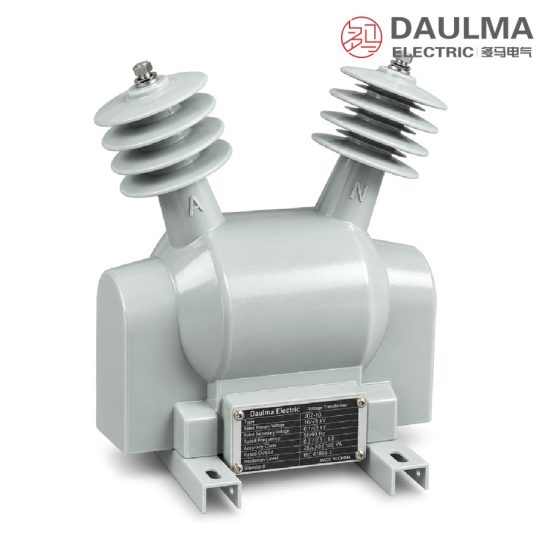
Product Overview
The FDGE11 outdoor dry type discharge coil is an epoxy resin vacuum-cast, single-phase, fully-enclosed outdoor product for AC power systems at 50Hz/60Hz with a rated voltage of 12kV and below. Connected in parallel with the high-voltage shunt capacitor bank, it provides a defined discharge path that reduces the residual voltage of the capacitor bank to a safe value within five seconds when the capacitor group is disconnected from the system, protecting operating personnel and downstream equipment.
The coil adopts a fully-enclosed post-type structure vacuum-cast with outdoor-grade epoxy resin, giving excellent arc resistance, UV resistance, anti-aging performance and long service life. During normal operation the secondary winding functions as a voltage indicator; where users require it, a residual voltage winding can be provided to deliver relay protection. The sealed secondary terminal box is both rain-proof and lightning-proof, making the unit compact, light-weight and maintenance-free — the ideal replacement for outdoor oil-immersed discharge coils.
Key Features:
- Discharges capacitor residual voltage to safe level within 5 seconds
- Fully-enclosed post-type structure vacuum-cast with outdoor epoxy resin
- Secondary winding for voltage indication; optional residual protection
- Rated voltage up to 12/√3 kV with matched discharge capacity of 3.4 Mvar
- Operates at -40°C to 40°C, altitude up to 3000m, surface creepage >420mm
- Oil-free dry type design ensures maintenance-free operation, long life
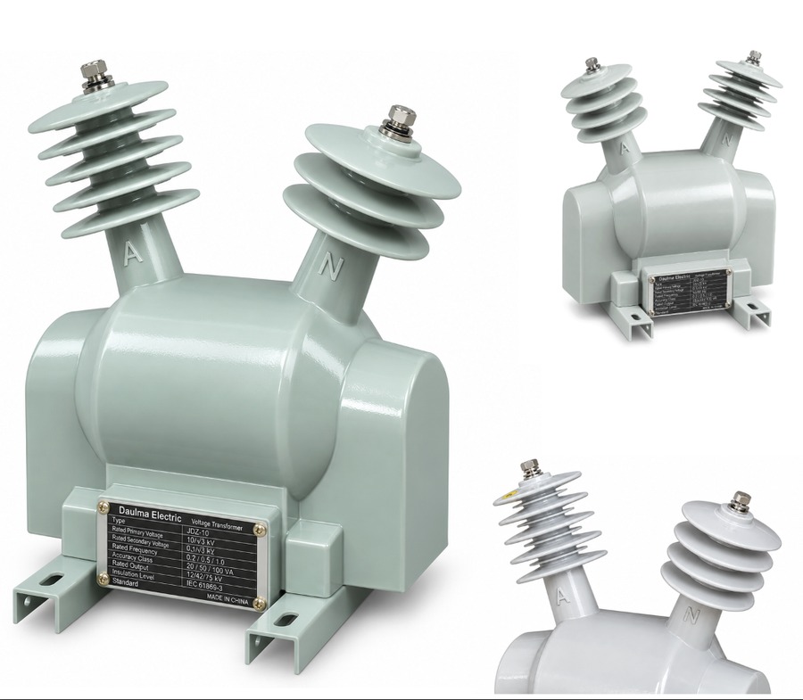
Product Display
Model Designation
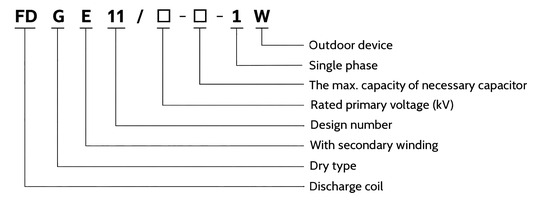
The FDGE11 model designation follows a standardized coding system:
Example: FDGE11/6.6/√3-1.7-1W denotes a dry-type outdoor fully-enclosed discharge coil with secondary winding, design No.11, rated primary voltage 6.6/√3 kV, matched capacitor capacity 1.7 Mvar, single phase, outdoor device.
Service Conditions
- Installation: Outdoor type
- Ambient Temperature: -40°C to +40°C
- Altitude: Not more than 3000m
- System Frequency: 50Hz / 60Hz
- Atmosphere: No corrosive gas; no conducting or explosive dust
- Surface Creepage Distance: More than 420mm
Construction
The FDGE11 uses an outdoor fully-enclosed vacuum-cast post-type structure. Because the whole unit is vacuum-cast with outdoor-grade epoxy resin, it combines arc resistance, UV resistance, anti-aging performance and a long service life. The secondary terminals are fully enclosed, preventing induced lightning over-voltage as well as rain ingress.
Construction Advantages: Small volume, light weight, low no-load loss, strong over-voltage withstand capability, convenient installation, no maintenance required, ideal replacement for outdoor oil-immersed discharge coils, weight approximately 29 kg.
Technical Data
| Type | Rated
Voltage Ratio (kV) |
Accuracy Class
& Rated Output (VA) |
Discharge
Capacity (Mvar) |
Rated
Insulation Level (kV) |
|---|---|---|---|---|
| FDGE11/6.6/√3-1.7-1W | 6.6/√3/0.1 | 0.2→20; 0.5→50; 1→100 | 1.7 | 7.2/32/60 |
| FDGE11/7.2/√3-1.7-1W | 7.2/√3/0.1 | 0.2→20; 0.5→50; 1→100 | 1.7 | 7.2/32/60 |
| FDGE11/11/√3-1.7-1W | 11/√3/0.1 | 0.2→20; 0.5→50; 1→100 | 1.7 | 12/42/75 |
| FDGE11/11/√3-2.5-1W | 11/√3/0.1 | 0.2→20; 0.5→50; 1→100 | 2.5 | 12/42/75 |
| FDGE11/11/√3-3.4-1W | 11/√3/0.1 | 0.2→20; 0.5→50; 1→100 | 3.4 | 12/42/75 |
| FDGE11/12/√3-1.7-1W | 12/√3/0.1 | 0.2→20; 0.5→50; 1→100 | 1.7 | 12/42/75 |
| FDGE11/12/√3-2.5-1W | 12/√3/0.1 | 0.2→20; 0.5→50; 1→100 | 2.5 | 12/42/75 |
| FDGE11/12/√3-3.4-1W | 12/√3/0.1 | 0.2→20; 0.5→50; 1→100 | 3.4 | 12/42/75 |
Standards
The FDGE11 series conforms to the DL/T 653 standard (Specification of discharge coils for high voltage parallel connection capacitor) and can be built to special customer demands. Load power factor: cosφ 0.8 (lagging), surface creepage distance: more than 420mm.
Installation & Dimensions
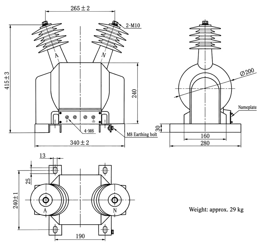
The FDGE11 discharge coil stands on a flat foundation. Overall dimensions: height 415±3 mm; top terminal spacing 265±2 mm with 2-M10 terminals; body height 240 mm; base 340±2 mm (width) × 280 mm (length); footprint 240±1 × 190 mm with 13×25 mm mounting slots; body diameter Ø200 mm; base thickness 30 mm; secondary terminal board 4-M6; M8 earthing bolt; weight approximately 29 kg. Refer to the approved outline drawing before foundation and busbar work.
Installation Diagram
Wiring Diagram
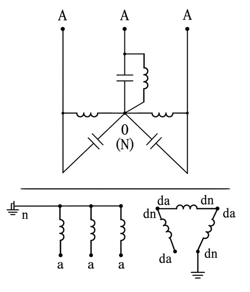
The primary winding (terminal A) is connected between the busbar and the neutral/earth point of the high-voltage capacitor bank (terminal N). The secondary winding supplies voltage indication; where fitted, the residual voltage winding connects to the protection relay. Confirm terminal markings, polarity and earthing against the approved wiring drawing before energization.