Product Overview
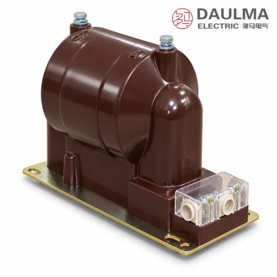
The FDGE9 fully-enclosed dry type discharge coil is an epoxy resin vacuum-cast, single-phase indoor product for AC power systems at 50Hz with a rated voltage of 10kV and below. Connected in parallel with the high-voltage shunt capacitor bank, it provides a defined discharge path that reduces the residual voltage of the capacitor bank to a safe value within five seconds when the capacitor group is disconnected from the system, protecting operating personnel and downstream equipment.
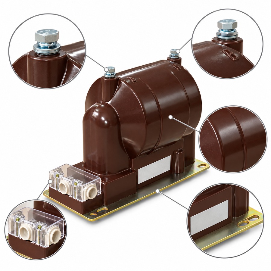
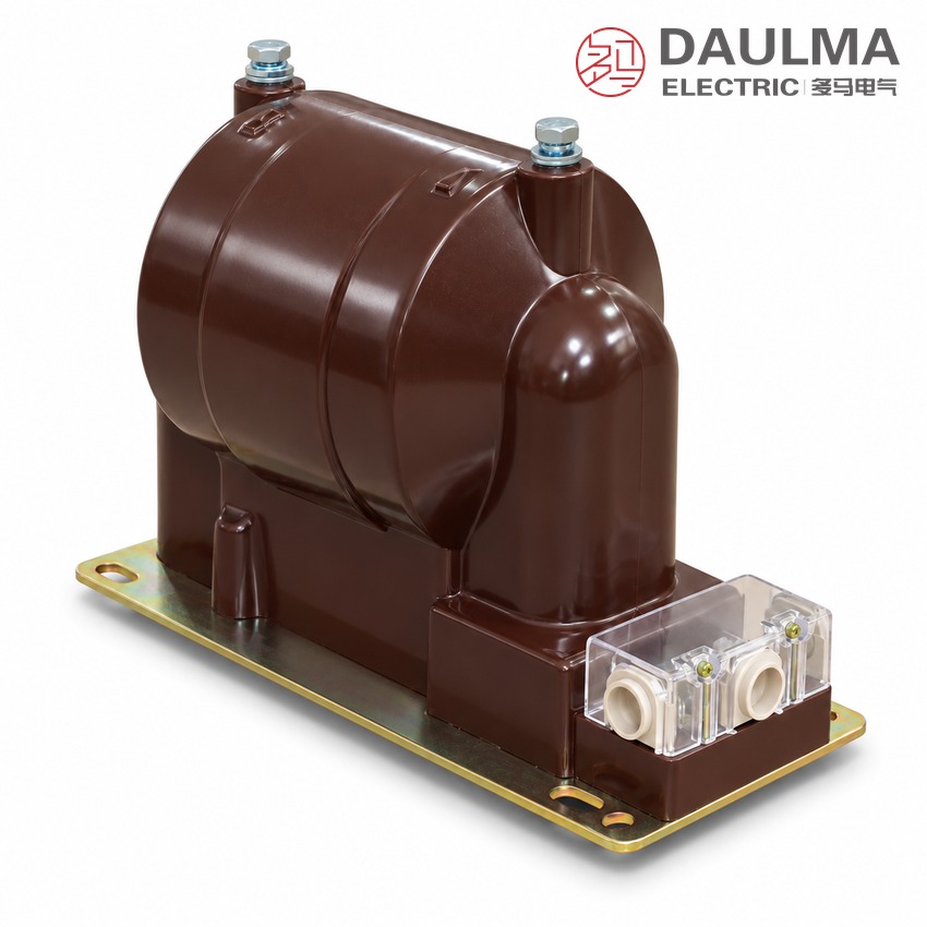
The coil adopts a fully-enclosed cast structure in which the iron core, primary winding and secondary winding are cast together by advanced vacuum casting. During normal operation the secondary winding functions as a voltage indicator; where users require it, a residual voltage winding can be provided to deliver relay protection. The sealed body keeps the core and windings free of dust and moisture, giving a compact, light-weight, maintenance-free unit designed to replace conventional oil-immersed discharge coils.
Key Features:
- Epoxy vacuum-cast structure seals core and windings against dust
- Discharges capacitor residual voltage to safe levels in five seconds
- Secondary winding is a voltage indicator; residual winding for relay
- Rated 6.6-12kV with 1.7-3.4 Mvar discharge capacity for 50Hz systems
- Accuracy classes 0.2, 0.5, 1 with secondary outputs from 20 to 100VA
- Conforms to DL/T 653-1998; maintenance-free replacement for oil types
Product Display
Model Designation
The FDGE9 model designation follows a standardized coding system:
Example: FDGE9/11/√3-2.5-1 denotes a dry-type fully-enclosed discharge coil with secondary winding, design No.9, rated primary voltage 11/√3 kV, matched capacitor capacity 2.5 Mvar, single phase.
Service Conditions
- Installation: Indoor type
- Ambient Temperature: -5°C to +40°C
- Altitude: Not more than 1000m
- System Frequency: 50Hz
- Atmosphere: No corrosive gas or smoke; no conducting or explosive dust
- Vibration: No severe mechanical vibration at the installation site
- Relative Humidity: Monthly average ≤ 90%; daily average ≤ 95%
Construction
The FDGE9 uses a fully-enclosed structure. The magnetic core is wound from high-grade cold-rolled silicon-steel sheet, and the core together with the primary and secondary windings is cast as one body by advanced vacuum casting technique. The result is a small-volume, light-weight unit with low no-load loss, strong resistance to over-voltage, and convenient installation that needs no maintenance.
Construction Advantages: Fully-enclosed cast body seals the insulation system against dust and moisture, maintenance-free replacement for oil-immersed discharge coils in capacitor bank compensation installations.
Technical Data
| Type | Rated
Voltage (kV) |
Accuracy Class
& Rated Output (VA) |
Discharge
Capacity (Mvar) |
Rated
Insulation Level (kV) |
|---|---|---|---|---|
| FDGE9/6.6/√3-1.7-1 | 6.6/√3/0.1 | 0.2→20; 0.5→50; 1→100 | 1.7 | 7.2/32/60 |
| FDGE9/7.2/√3-1.7-1 | 7.2/√3/0.1 | 0.2→20; 0.5→50; 1→100 | 1.7 | 7.2/32/60 |
| FDGE9/11/√3-1.7-1 | 11/√3/0.1 | 0.2→20; 0.5→50; 1→100 | 1.7 | 12/42/75 |
| FDGE9/11/√3-2.5-1 | 11/√3/0.1 | 0.2→20; 0.5→50; 1→100 | 2.5 | 12/42/75 |
| FDGE9/11/√3-3.4-1 | 11/√3/0.1 | 0.2→20; 0.5→50; 1→100 | 3.4 | 12/42/75 |
| FDGE9/12/√3-1.7-1 | 12/√3/0.1 | 0.2→20; 0.5→50; 1→100 | 1.7 | 12/42/75 |
| FDGE9/12/√3-2.5-1 | 12/√3/0.1 | 0.2→20; 0.5→50; 1→100 | 2.5 | 12/42/75 |
| FDGE9/12/√3-3.4-1 | 12/√3/0.1 | 0.2→20; 0.5→50; 1→100 | 3.4 | 12/42/75 |
Standards
The FDGE9 series conforms to the DL/T 653-1998 standard (Specification of discharge coils for high voltage parallel connection capacitor for order). Load power factor: cosφ 0.8 (lagging), surface creepage distance: more than 300mm.
Installation & Dimensions
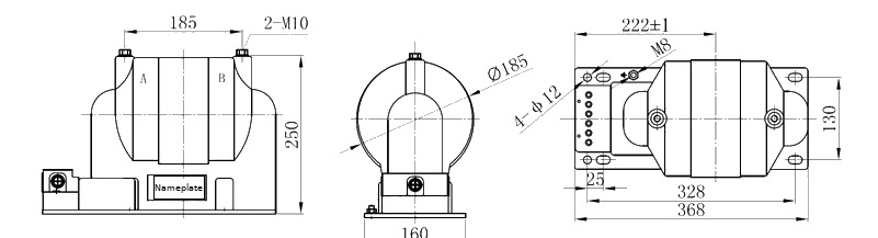
The FDGE9 discharge coil is designed for indoor installation. Overall dimensions: length 368 mm; width 222±1 mm; height 250 mm; body diameter Ø185 mm; base fixing 4-Ø12 with 25mm slot offset; top terminals 2-M10; side mounting M8. Refer to the approved outline drawing before foundation and busbar work.
Installation Diagram
Wiring Diagram
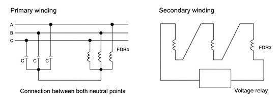
The primary winding is connected in parallel across the high-voltage capacitor bank terminals (phase to neutral/earth point of the bank). The secondary winding supplies voltage indication; where fitted, the residual voltage winding connects to the protection relay. Confirm terminal markings, polarity and earthing against the approved wiring drawing before energization.
FAQs