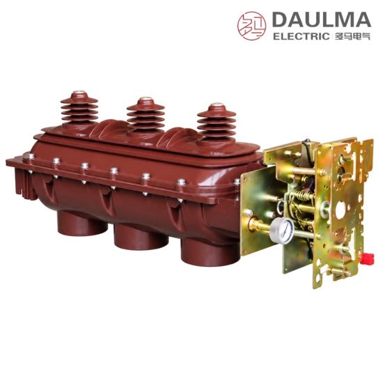
Product Overview
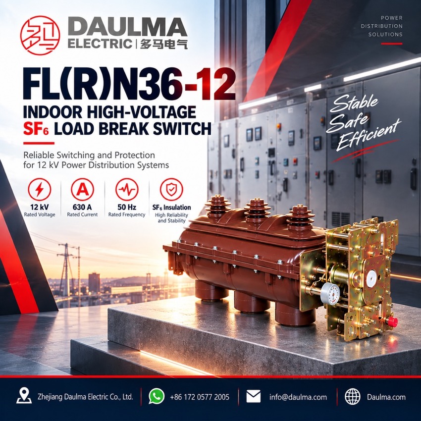
The FLN36-12 indoor high-voltage SF6 load break switch is a three-phase switching device for 10/12 kV, 50 Hz distribution systems, developed from absorbed foreign technology and built to local operating requirements. Full type tests confirm conformity with GB 3804 for 3-63 kV AC load break switches, GB 16926 for load break switch-fuse combination units, and IEC 60265 and IEC 60420. The series covers the plain load break switch, the FLRN36-12 load break switch-fuse combination unit, and cable-head versions for cable branch boxes, so the same frame serves switching, isolation and earthing duties in urban networks, industrial plants, high-rise buildings, residential districts and package substations.
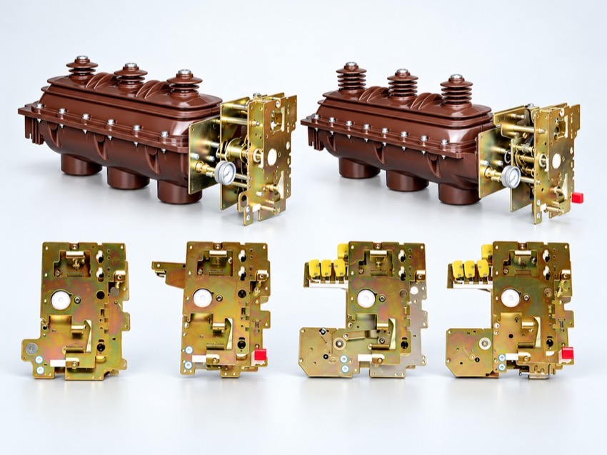
Product Display
Model Designation
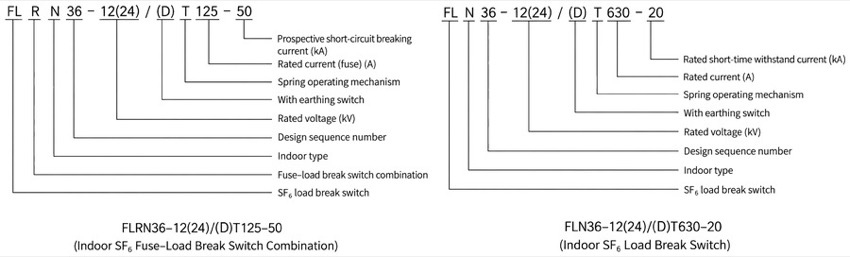
Model format: FLN36-12(24)/(D)T 630-20 (load break switch) and FLRN36-12 (switch-fuse combination unit)
- FL: SF6 load break switch; N: indoor type; 36: design sequence number
- 12 (24): rated voltage, kV
- D: with earthing switch; T: spring operating mechanism
- 630: rated current, A; 20: rated short-time withstand current, kA
- R after FL: fuse combination; trailing figures give fuse rated current and prospective short-circuit breaking current
- Other voltage, current and fuse combinations are available on request
Service Conditions
- Ambient temperature: +40 °C maximum, -25 °C minimum
- Altitude: not more than 1000 m
- Relative humidity: daily average not more than 95%, monthly average not more than 90%
- Seismic intensity: not more than 8 degrees
- Site condition: no fire, explosion, chemical corrosion or severe vibration
- Pollution level: II
Construction
The three poles are carried on a steel frame with epoxy insulator columns and house a sealed SF6 interrupter with on-off-earth three-position action and reliable interlocking. The design gives high break-point insulation and a large creepage distance, with a grading shield covering the outgoing terminals.
Dynamic and static seals keep the gas chamber tight while a clearly visible pressure gauge allows the sealed system to be monitored in service. Versions for cable heads accept touch-safe elbow connectors on the outgoing terminals for use in cable branch and ring main units.
Technical Data
| No. | Item | Unit | FLN36-12 | FLRN36-12 |
|---|---|---|---|---|
| 1 | Rated voltage / highest voltage | kV | 10/12 | 10/12 |
| 2 | Rated current | A | 630 | 125 (fuse) |
| 3 | Rated short-time withstand current (3 s) | kA | 20 | — |
| 4 | Rated peak withstand and short-circuit making current | kA | 50 | 80 |
| 5 | Rated short-circuit breaking current | kA | — | 31.5 |
| 6 | Rated transfer current | A | — | 2000 |
| 7 | Power-frequency / lightning impulse withstand voltage | kV | 42/75 | 42/75 |
| 8 | Mechanical life | operations | 3000 | 3000 |
| 9 | Rated SF6 gas pressure | MPa | 0.045 | 0.045 |
Standards
Full type tests confirm conformity with GB 3804 for 3-63 kV AC high-voltage load break switches, GB 16926 for high-voltage load break switch-fuse combination units, IEC 60265 for indoor high-voltage switch-disconnectors, fuses and switch-fuse combinations, and IEC 60420 for high-voltage alternating-current switch-fuse combinations.
Installation & Dimensions
Installation Diagram
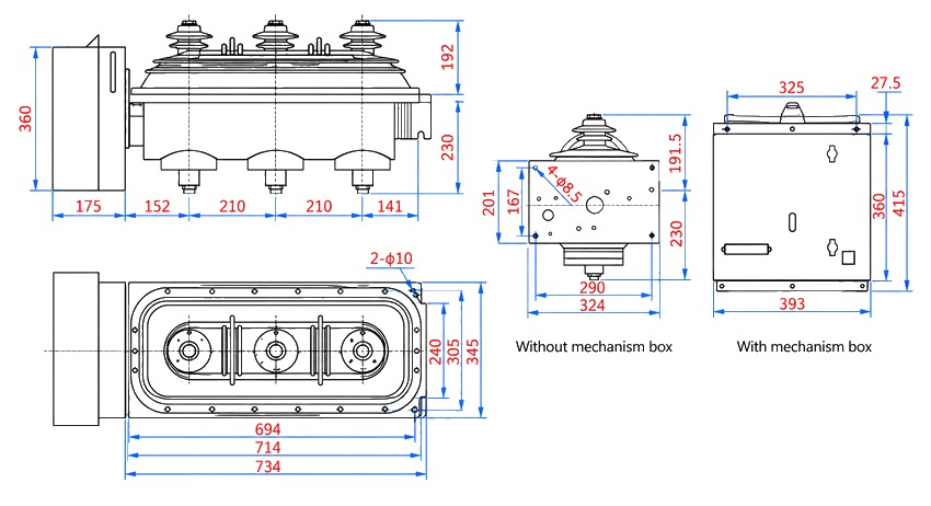
The frame is fixed level inside the switchgear cubicle or ring main unit, and the earthing terminal is bonded to the earth grid with a dedicated conductor. Verify the on-off-earth three-position indication and the interlocking action, confirm that the spring mechanism charges and releases smoothly, and check that the SF6 pressure gauge reads within the specified range before the power-frequency withstand test on the main circuit.
| Dimension | Value (mm) |
|---|---|
| Single pole height / width / depth | 360 / 192 / 230 |
| Three-pole width, 125 A / 200 A / 630 A | 694 / 714 / 734 |
| Fixing centres, 125 A / 200 A / 630 A | 240 / 305 / 345 |
| Front flange holes | 4 × Ø10 |
| Side flange holes | Ø8.5 |
| Cubicle depth with spring mechanism box | 325 |