Aperçu du produit
Définition fonctionnelle
The JLSZW3-6 and JLSZW3-10 series pour extérieur type sec combined transformateurs de mesure are integrated electromagnetic measurement devices that combine transformateur de tension (tt) (VT) and transformateur de courant (tc) (CT) functions in a single sealed enclosure. These transformers provide simultaneous voltage and current measurement for three-phase AC power systèmes rated at 50 Hz, with classe de tension systèmees of 6 kV and 10 kV. The combined configuration delivers galvanically isolated secondary signals for comptage d’énergie, protection relaying, and supervisory control applications in urban/rural grids, pour extérieur substations, and industrial distribution networks.
Caractéristiques principales
| Article | Spécification (per order / nameplate) |
|---|---|
| Classe de tension système | 6 kV / 10 kV class (pour extérieur distribution applications) |
| Fréquence assignée | 50 Hz (60 Hz available upon request) |
| VT voltage ratios | 3000/100 V, 6000/100 V, 10000/100 V |
| VT classes de précision | 0.2 / 0.5 |
| VT puissance assignée | 15 VA / 30 VA per noyau |
| VT limit output | 300 VA |
| CT current ratios | 5~200/5 A |
| CT classes de précision | 0.2S / 0.2 |
| CT puissance assignée | 10 VA per noyau |
| CT tenue au court-circuit | Ith: 100 × I₁n (1 s), Idyn: 2.5 × Ith (peak) |
| VT niveau d’isolement (JLSZW3-6) | 7.2/32/60 kV |
| VT niveau d’isolement (JLSZW3-10) | 12/42/75 kV |
| CT niveau d’isolement | 12/42/75 kV |
| Connection configuration | Three-phase four-wire Y/Yo |
| Normes applicables | GB 20840.4-2015 (Combined); GB 20840.2-2014, GB 20840.1-2010 (CT); GB 20840.3-2013, GB 20840.1-2010 (VT) |
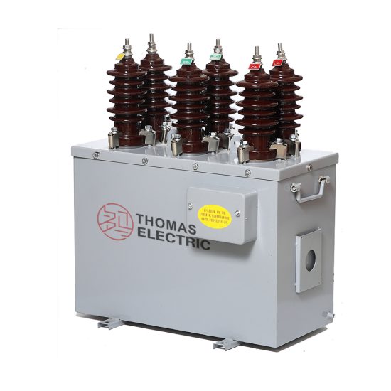
Présentation du produit
 Thomas Electric")
Principe de fonctionnement
The transformateur combiné integrates independent voltage and current measurement functions using electromagnetic induction principles. The transformateur de tension (tt) section employs a wound-noyau configuration with primary enroulements connected to the power système and secondary enroulements delivering standardized 100 V output. The transformateur de courant (tc) section utilizes toroidal noyaus with conducteur primaires passing through apertures and secondary enroulements providing 5 A output current proportional to primary current. Both VT and CT sections operate simultaneously to supply complete three-phase voltage and current signals for mesurage instruments, protective relays, and monitoring systèmes.
Position d’application système
- Pour extérieur Distribution Networks: 6-10 kV overhead lines and pole-mounted switchgear
- Comptage d’énergie Stations: Revenue-grade three-phase electricity measurement and billing
- Protection Systèmes: Overcurrent, overvoltage, and directional protection schemes
- Substation Monitoring: Remote terminal units (RTU) and SCADA data acquisition
- Industrial Power Systèmes: Factory distribution panels and pour extérieur transformer stations
Aperçu structurel
The transformateur combiné features fully-enclosed metal housing with integrated résine époxy cast VT and CT components. The transformateur de tension (tt) sections use exposed iron noyaus with high-quality cold-rolled grain-oriented silicon steel, with primary and secondary enroulements wound on noyau limbs. Current transformer sections employ closed iron noyaus with premium silicon steel, ensuring measurement accuracy and stability. Three transformateurs de tension and three transformateurs de courant are assembled in a sealed metal enclosure, providing compact installation footprint, environmental protection, and reliable long-term operation in pour extérieur conditions.
Désignation du modèle
 Thomas Electric")
Explication du code
- J — Voltage transformer (VT/PT)
- L — Current transformer (CT)
- S — Three-phase configuration
- Z — Cast-resin (epoxy) insulated structure
- W — Pour extérieur installation type
- 3 — Design series code
- 6 / 10 — Voltage class (kV)
Description
JLSZW3-6 and JLSZW3-10 designate the classe de tension système (6 kV or 10 kV). The transformateur combiné integrates three single-phase transformateurs de tension and three single-phase transformateurs de courant in Y/Yo three-phase four-wire connection. The specific voltage ratio, current ratio, classes de précision, and charge assignées are defined by project spécification and confirmed on the nameplate.
Conditions de service
The JLSZW3 series transformateur combinés are designed for pour extérieur operation under normal conditions de service in medium-voltage distribution systèmes.
- Environnement d’installation: Pour extérieur installation in sheltered or exposed locations
- Altitude: Not exceeding 1000 m above sea level (higher altitude applications require engineering confirmation)
- Température ambiante: −25 °C to +40 °C
- Humidité relative: Daily average ≤ 95%, monthly average ≤ 90% (at +20 °C reference)
- Conditions environnementales: Free from severe salt fog, industrial contamination, or explosive atmospheres; no abnormal vibration or mechanical shock
- Lightning protection: Zinc oxide surge arrester required within 1 meter of installation point
Construction
Conception de construction
Transformateur de tension (TT) Section:
- Noyau type: Wound noyau with exposed structure
- Noyau material: High-quality cold-rolled grain-oriented silicon steel sheets
- Isolation: Epoxy resin cast construction
- Enroulements: Primary and secondary coils wound on noyau limbs
Transformateur de courant (TC) Section:
- Noyau type: Closed ring-type iron noyau
- Noyau material: Premium quality silicon steel laminations
- Isolation: Epoxy resin monolithic casting
- Configuration: Pass-through primary with secondary enroulements on toroidal noyau
Enclosure Assembly:
- Housing: Sealed metal cabinet with environmental protection
- Components: Three VT units + three CT units in integrated assembly
- Terminals: Primary and secondary terminal blocks accessible via compartment doors
- Protection rating: Weather-resistant construction for pour extérieur service
The résine époxy casting provides stable isolation properties, moisture resistance, pollution resistance, and aging resistance for reliable pour extérieur operation. The fully-enclosed metal housing protects components from environmental exposure while maintaining electrical clearances and creepage distances.
Terminal Arrangement & Marking
 Thomas Electric")
Transformateur de tension (TT) Terminals:
- Bornes primaires (per phase): A / B / C / N (neutral)
- Bornes secondaires (per phase): a / b / c / n (neutral)
- Connection: Y/Yo three-phase four-wire configuration
Transformateur de courant (TC) Terminals:
- Bornes primaires (per phase): P1 / P2
- Bornes secondaires (Phase A): 1K1 / 1L1
- Bornes secondaires (Phase B): 1K2 / 1L2
- Bornes secondaires (Phase C): 1K3 / 1L3
Terminal markings follow standard polarity conventions per GB 20840 series. Correct terminal identification is essential for accurate mesurage and proper protection relay operation. Wiring diagrams and terminal assignment are provided with each unit.
Données techniques
Transformateur de tension (TT) Spécifications
| Model | Rated Voltage Ratio (V) |
Accuracy Class |
Rated Output (VA) |
Limit Output (VA) |
Rated Isolation Level (kV) |
|---|---|---|---|---|---|
| JLSZW3-6 | 3000/100 | 0.2 / 0.5 | 15 / 30 | 300 | 3.6/25/40 |
| 6000/100 | 7.2/32/60 | ||||
| — | — | ||||
| JLSZW3-10 | 3000/100 | 0.2 / 0.5 | 15 / 30 | 300 | 3.6/25/40 |
| 6000/100 | 7.2/32/60 | ||||
| 10000/100 | 12/42/75 |
Transformateur de tension (TT) Notes:
- Accuracy class 0.2 for precision mesurage; 0.5 for general mesurage applications
- Rated output (burden) available as 15 VA or 30 VA per secondary winding
- Limit output capacity: 300 VA continuous
- Niveau d’isolement format: Um/ACSD/LI (système voltage / short-duration power-frequency / lightning impulse)
- Secondary voltage: 100 V line-to-neutral (57.7 V phase-to-neutral in Y connection)
Transformateur de courant (TC) Spécifications
| Model | Rated Current Ratio (A) |
Accuracy Class |
Rated Output (VA) |
Rated Short-Time Thermal Current (kA) |
Rated Dynamic Stability Current (kA peak) |
Rated Isolation Level (kV) |
|---|---|---|---|---|---|---|
| JLSZW3-6 | 5~200/5 | 0.2S | 10 | 100 × I₁n | 2.5 × Ith | 12/42/75 |
| 0.2 | ||||||
| JLSZW3-10 | 5~200/5 | 0.2S | 10 | 100 × I₁n | 2.5 × Ith | 12/42/75 |
| 0.2 |
Transformateur de courant (TC) Notes:
- Accuracy class 0.2S for electronic energy meters (extended range); 0.2 for standard mesurage
- Courant primaire assigné (I₁n) selectable from 5 A to 200 A in standard steps
- Courant secondaire assigné: 5 A (1 A available as special order)
- Short-time thermal current (Ith): 100 times courant primaire assigné for 1 second
- Dynamic stability current (Idyn): 2.5 times Ith (peak value)
- Burden power factor: cosφ = 0.8 (inductive) unless otherwise specified
Accuracy and Burden
Transformateur de tension (TT) Accuracy Performance:
Voltage transformers meet classe de précision 0.2 or 0.5 requirements per GB 20840.3-2013 at charge assignée from 25% to 100% of rated voltage. Ratio error and phase displacement remain within specified limits across the operating range.
Transformateur de courant (TC) Accuracy Performance:
Current transformers meet classe de précision 0.2S or 0.2 requirements per GB 20840.2-2014. Class 0.2S provides extended accuracy range from 1% to 120% of courant primaire assigné, suitable for electronic energy meters. Accuracy limits are maintained at charge assignée and fréquence assignée.
Burden Selection:
VT charge assignée (15 VA or 30 VA) shall accommodate total connected load including meters, relays, and wiring resistance. CT charge assignée (10 VA) shall cover circuit secondaire impedance at rated current (5 A). Actual burden should be verified during système design to ensure accuracy compliance.
Conformité aux normes
Applicable Normes
- GB 20840.4-2015: Instrument transformers – Part 4: Additional requirements for transformateur combinés
- GB 20840.2-2014: Instrument transformers – Partie 2: Additional requirements for transformateurs de courant
- GB 20840.1-2010: Instrument transformers – Partie 1: Exigences générales
- GB 20840.3-2013: Instrument transformers – Part 3: Additional requirements for inductive transformateurs de tension
- IEC 61869 series: Instrument transformers (reference standard)
Testing and Acceptance
Each transformateur combiné unit undergoes factory testing per normes applicables:
- Tests de routine: Voltage ratio, current ratio, polarity, accuracy, burden, isolation resistance, dielectric withstand
- Isolation test: Power-frequency voltage withstand test on primary and circuit secondaires
- Lightning impulse test: Full-wave impulse voltage test per niveau d’isolement spécification
- Tenue au court-circuit test: Verification of Ith and Idyn ratings (type test or calculation)
- Inspection visuelle et dimensionnelle: Nameplate data, terminal marking, workmanship verification
- Special tests: Partial discharge measurement, temperature rise test (where specified)
Installation & Dimensions
Installation Guidelines
- Combined transformer shall be mounted on stable foundation or pole-mounted bracket with secure mechanical fixing
- Mounting position shall provide dégagement adéquat for electrical safety, heat dissipation, and maintenance access
- Primary connections made via busbar or cable termination as specified by project design
- Circuit secondaires routed through cable glands with proper sealing and strain relief
- Surge arrester installation mandatory within 1 meter of bornes primaires per GB requirements
- Grounding connection required on designated terminal following local electrical codes
Contours
JLSZW3-6kV / 10kV Transformateur combiné
 Thomas Electric")
Note: Dimensional drawings show typical configuration. Actual dimensions confirmed on approved drawings prior to manufacture. Mounting hole patterns and terminal locations may vary by spécification.
Notes de sécurité
- VT circuit secondaire should not be short-circuited during operation; miniature circuit breaker or fuse protection recommended
- CT circuit secondaire must never be open when primary carries current; dangerous high voltage will appear at bornes secondaires
- Pendant l’inspection or maintenance, CT secondary shall be short-circuited before disconnecting any instruments or wiring
- Un point of VT secondary neutral and un point of CT circuit secondaire shall be reliably grounded per normes applicables
- Toute installation and maintenance operations shall comply with national and local electrical safety regulations
- De-energize primary circuit and verify absence of voltage before accessing terminal compartments
Informations de commande
Lors de la commande, the required configuration shall be specified according to local utility requirements, normes applicables, and project technical spécification. The following parameters shall be clearly stated for technical confirmation and production release:
Transformateur de tension (TT) Requirements:
- Rated primary voltage / voltage ratio: 3000/100 V, 6000/100 V, or 10000/100 V
- Accuracy class: 0.2 or 0.5
- Charge assignée: 15 VA or 30 VA per secondary winding
- Niveau d’isolement: Per classe de tension système and project spécification
Transformateur de courant (TC) Requirements:
- Courant primaire assigné / transformation ratio: 5/5 A through 200/5 A in standard steps
- Accuracy class: 0.2S or 0.2
- Charge assignée: 10 VA per secondary winding
- Tenue au court-circuit: Ith (1 s) and Idyn (peak) per système fault level
Système and Configuration:
- Classe de tension système: 6 kV or 10 kV
- Fréquence assignée: 50 Hz (specify if 60 Hz required)
- Connection type: Three-phase four-wire Y/Yo (standard)
- Installation type: Pour extérieur pole-mounted or foundation-mounted
If special requirements apply (non-standard ratios, additional accuracy noyaus, special terminal arrangements, mounting configurations, documentation language, certificates, or factory testing beyond routine), specify them at ordering stage for technical review and confirmation. Custom configurations require engineering approval and final datasheet before production release.