Product Overview
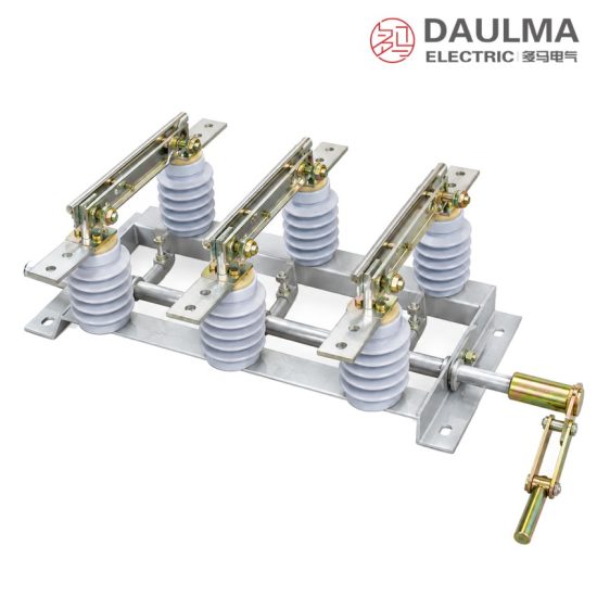
The GN19-12 is an indoor high-voltage disconnector for three-phase AC 50 Hz systems of 12 kV and below, supplied with a CS6-1 manual operating mechanism. It makes and breaks circuits under voltage but without load and provides a visible break. The three poles are assembled on one common steel frame, porcelain insulators carrying the knife blades and static contacts, and are coupled to a single operating shaft so the set is installed and operated as one unit. Four ratings cover 400 A to 1250 A; pollution-proof, high-altitude, wall-mounted C and live-display versions are available.
Product Display
Model Designation
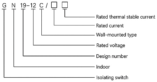
Model format: G N19-12 C/□□
- G – isolating switch (disconnector)
- N – indoor place of use
- 19 – design sequence number
- 12 – rated voltage, kV
- C – wall-mounted type (omitted for the standard type)
- □ – rated current, A
- □ – rated thermal stable current, kA
Service Conditions
- Altitude: not exceeding 1000 m
- Ambient air temperature: -25 °C to +40 °C
- Relative humidity: daily average value not more than 95% and not more than 90%
- Seismic intensity: not above intensity 8
- Installation site free from fire hazard, flammable or explosive substances, severe pollution, chemical corrosion and violent vibration
Construction
The three poles are mounted on one common steel frame with 250 mm phase spacing (250 + 250 mm) and a 700 mm mounting span, giving an overall width of 948 mm for the complete set. Each pole carries the knife blade and the static contact on porcelain support insulators, and copper terminals at the top and bottom of the frame take the busbar or cable connections.
A CS6-1 manual operating mechanism drives the operating shaft across the frame; the side handle gives a positive make and break action, the blades are clearly visible in the open position, and the outline drawing calls for an operating space of not less than 150 mm for full handle travel. The wall-mounted C version is arranged for mounting through the cubicle wall so circuits can be brought out on both sides of the panel, and pollution-proof and high-altitude versions plus a live-display device cover severe site conditions.
Technical Data
| Model | Rated voltage (kV) | Rated current (A) | 4 s thermal stable current (kA) | Dynamic stability current (kA) |
|---|---|---|---|---|
| GN19-10C/400-12.5 | 12 | 400 | 12.5 | 31.5 |
| GN19-10C/630-20 | 12 | 630 | 20 | 50 |
| GN19-10C/1000-31.5 | 12 | 1000 | 31.5 | 80 |
| GN19-10C/1250-40 | 12 | 1250 | 40 | 100 |
Standards
The source datasheet names no specific product standard for the GN19-12 series. The ratings apply as fixed by the ordered type designation – the rated current and the rated thermal stable current are stated in the designation itself – under the order technical agreement, and the final data follow the nameplate and the documents shipped with the switchgear.
Installation & Dimensions
Installation Diagram
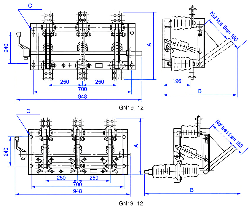
Fix the complete three-pole set to the switchgear frame through the holes dimensioned C, bolt the busbar or cable conductors to the copper terminals, and couple the CS6-1 manual operating mechanism to the operating shaft, leaving at least 150 mm clear for handle travel. Before energising, check that the blades seat fully home and open to the full visible gap. Note: the catalogue tabulates two dimension sets (A, B, C) for each current rating without indicating which arrangement each set applies to – confirm the applicable set with the ordering technical conditions.
| Model | Set 1: A (mm) | Set 1: B (mm) | Set 1: C (mm) | Set 2: A (mm) | Set 2: B (mm) | Set 2: C (mm) |
|---|---|---|---|---|---|---|
| Three-pole set, fixed dimensions | Overall width 948 | Phase spacing 250 + 250 | Mounting span 700 | Frame height 240 | Side depth 196 | Operating clearance ≥ 150 |
| GN19-12/400 | 450 | 436 | 4 × 14 × 24 | 420 | 625 | 4 × 18 × 24 |
| GN19-12/630 | 490 | 436 | 4 × 14 × 24 | 4460 | 625 | 4 × 18 × 24 |
| GN19-12/1000 | 510 | 530 | 4 × 18 × 28 | 505 | 745 | 4 × 18 × 28 |
| GN19-12/1250 | 510 | 530 | 4 × 18 × 28 | 505 | 745 | 4 × 18 × 28 |