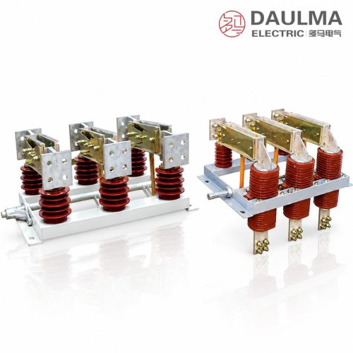
Product Overview
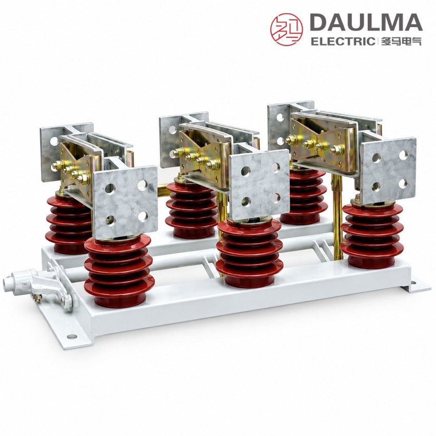
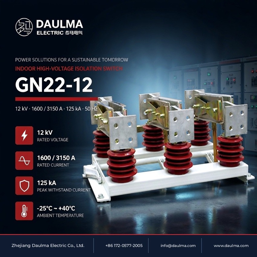
The GN22-12 is an indoor high-current high-voltage AC disconnector for three-phase 50 Hz switchgear rated 12 kV, offered in two current groups – 1600-2000 A and 2500-3150 A – with 4 s short-time withstand up to 50 kA and peak withstand up to 125 kA. Each pole uses post insulators and heavy copper knife and contact systems on a common steel frame, coupled by a linkage shaft and driven by a manual mechanism. Under voltage but without load it connects, interrupts or transfers circuits and gives a visible insulating break, suiting generator leads, bus sections and feeders in indoor cubicles.
Product Display
Model Designation
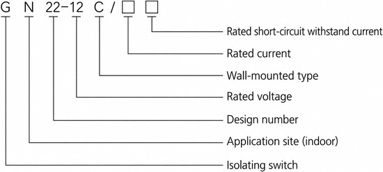
Model format: G N 22-12 C / □ □
- G – disconnector
- N – place of use: indoor
- 22 – design sequence number
- 12 – rated voltage in kV
- C – wall-through type
- First □ – rated current in A
- Second □ – rated short-circuit withstand current in kA
Service Conditions
- Altitude: up to 1000 m
- Ambient temperature: not above +40 ℃ and not below -25 ℃
- Relative humidity: daily average not above 95%, monthly average not above 90%
- Water-vapour pressure: daily average not above 2.2 × 10⁻³ MPa, monthly average not above 1.8 × 10⁻³ MPa
- Site free from fire, explosion, corrosion of metals, harmful gases that damage insulation and conductive dust
Construction
Each pole uses support post insulators and heavy copper knife and contact systems sized for 1600 to 3150 A, mounted on a common steel frame. The three poles are coupled by a linkage shaft and driven by a manual operating mechanism with open/closed position indication, and opening the knives gives a clearly visible insulating gap for safe maintenance.
The C wall-through version brings the current conductors through the panel wall so the disconnector can isolate a section on each side of the cubicle. The disconnector is interlocked with the associated circuit breaker because it makes and breaks circuits under voltage but without load and cannot break load or short-circuit current.
Technical Data
| Item | Unit | 1600 – 2000 A | 2500 – 3150 A |
|---|---|---|---|
| Rated voltage | kV | 12 | 12 |
| Rated frequency | Hz | 50 | 50 |
| Rated current | A | 1600 – 2000 | 2500 – 3150 |
| Rated short-time withstand current | kA | 40 | 50 |
| Rated peak withstand current | kA | 100 | 125 |
| Rated short-circuit duration | s | 4 | 4 |
| 1 min power-frequency withstand voltage (between poles / pole-to-earth) | kV | 42 | 42 |
| 1 min power-frequency withstand voltage (across the break) | kV | 49 | 49 |
| Lightning impulse withstand voltage, peak (between poles / pole-to-earth) | kV | 75 | 75 |
| Lightning impulse withstand voltage, peak (across the break) | kV | 85 | 85 |
Standards
The source page quotes no specific product standard for the GN22-12. Rated parameters and insulation levels are as tabulated by the manufacturer – 12 kV class, 4 s short-circuit duration – and the delivered switch is supplied to the order technical agreement and nameplate.
Installation & Dimensions
Installation Diagram
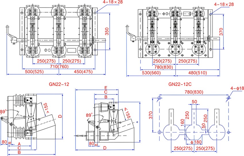
Mount the poles on the common steel frame inside the cubicle at the specified phase spacing and fix the frame through the 4 × 18 × 28 mm mounting holes; for the C version pass the wall-through bushings through the panel opening. Couple the poles to the operating mechanism, then verify free travel, correct contact seating and the full visible break before energising, and bond the frame to the earth network. All outline and mounting dimensions are in mm and correspond to the catalogue outline drawing.
| Type designation | A | B | C | D | E |
|---|---|---|---|---|---|
| GN22-12/1600-2000 | 255 | 305 | 527 | 490 | 50 |
| GN22-12/2500-3150 | 262 | 325 | 538 | 494 | 60 |
| GN22-12C/1600-2000 | 537 | 255 | 305 | 807 | 580 |
| GN22-12C/2500-3150 | 539 | 267.5 | 330 | 880 | 630 |