Article Content
ZJC-10Q 11kV Cast-Resin Current Transformer for Substation Metering and Protection – IEC 61869-2 Certified
Introduction to the ZJC-10Q Current Transformer
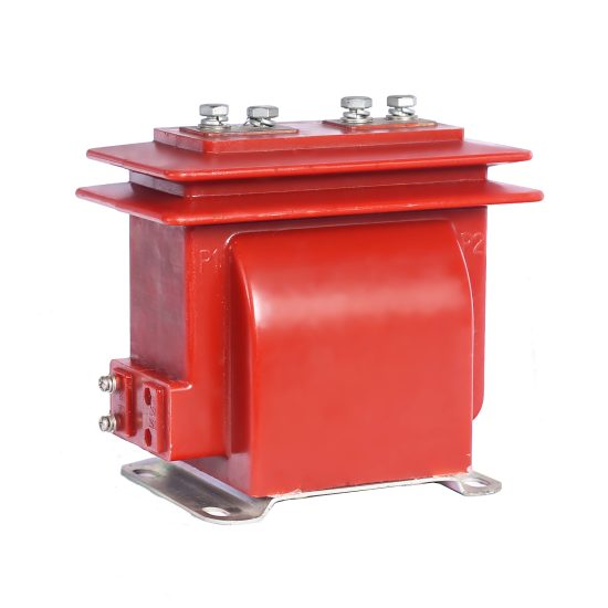
The ZJC-10Q is a medium-voltage cast-resin current transformer (CT) engineered for reliable operation in 11kV (IEC-rated) or 10kV (domestic system) networks. Designed in strict compliance with IEC 61869-2 and GB/T 20840.2, this instrument transformer serves dual roles in accurate energy metering and dependable protective relaying. Its construction leverages vacuum pressure impregnation (VPI) epoxy resin technology, which fully encapsulates the magnetic core and primary conductor, eliminating air voids and moisture ingress pathways that compromise long-term dielectric integrity.
Operating Principle of Cast-Resin Insulation
Cast-resin insulation in the ZJC-10Q employs a two-component cycloaliphatic epoxy resin system cured under controlled temperature and vacuum conditions. This process ensures complete impregnation of the grain-oriented electrical steel (GOES) core laminations and primary winding, resulting in a monolithic, void-free structure. The absence of internal cavities prevents partial discharge inception even under transient overvoltages, a critical requirement for IEC 61869-2 compliance. The resin’s high tracking resistance (>600 V according to IEC 60112) and thermal class F rating (155°C) guarantee stable performance across ambient temperatures from –25°C to +40°C. Unlike oil-filled alternatives, the solid dielectric eliminates fire hazards, environmental contamination risks, and maintenance-intensive oil sampling protocols.
Advantages Over Oil-Immersed Designs
Compared to traditional oil-immersed CTs, the ZJC-10Q offers superior safety, reduced lifecycle costs, and enhanced mechanical robustness. The absence of flammable insulating oil eliminates explosion and fire propagation risks—particularly vital in indoor substations or urban installations. Maintenance requirements are significantly lower: no oil level checks, dielectric loss tangent (tan δ) measurements, or moisture content analysis are needed. The unit’s compact footprint (typically 220 mm height × 180 mm diameter for standard ratios) facilitates retrofitting into existing switchgear bays. Additionally, the homogeneous thermal expansion coefficient between epoxy resin and copper windings minimizes stress-induced microcracks during thermal cycling, extending service life beyond 30 years under normal operating conditions.
Typical Application Overview
The ZJC-10Q is deployed across diverse 11kV infrastructure, including utility distribution substations, industrial plant switchyards, renewable energy collector systems, and commercial building main incomers. It supports both metering-class (e.g., 0.2S, 0.5) and protection-class (e.g., 5P10, 5P20) secondary windings within a single housing, enabling concurrent revenue-grade energy measurement and fault detection. Its robust short-time thermal withstand capability (typically 20 kA for 1 second) ensures survival during downstream short circuits without saturation-induced measurement errors.
Technical Specifications
The ZJC-10Q adheres to stringent dimensional, electrical, and environmental parameters defined by international and domestic standards. Below is a representative specification table for a standard single-ratio unit:
| Parameter | Value |
|---|---|
| Rated System Voltage (IEC) | 11 kV |
| Domestic System Voltage | 10 kV |
| Primary Current Rating | 50–3000 A (standard); up to 4000 A (custom) |
| Secondary Current | 1 A or 5 A |
| Accuracy Classes | Metering: 0.2S, 0.5; Protection: 5P10, 5P20 |
| Rated Burden | 5–30 VA per class (e.g., 15 VA @ 0.2S; 30 VA @ 5P20) |
| Insulation Level (IEC 60071-1) | Power Frequency Withstand: 28 kV rms / 1 min Lightning Impulse Withstand: 75 kV peak |
| Short-Time Thermal Current | 20 kA / 1 s (standard); 25 kA / 1 s (optional) |
| Dynamic Withstand Current | 50 kA peak |
| Ambient Temperature Range | –25°C to +40°C |
| Relative Humidity | ≤95% (non-condensing) |
| Maximum Altitude | 1000 m above sea level (derating required >1000 m) |
Standard Service Conditions
The ZJC-10Q is rated for continuous operation under IEC 60071-1 standard atmospheric conditions: ambient temperature not exceeding +40°C (with 24-hour average ≤35°C), relative humidity up to 95% at +25°C, and installation altitude ≤1000 m. At altitudes between 1000–2000 m, the power frequency withstand voltage must be derated by 1% per 100 m increment above 1000 m. For example, at 1500 m, the test voltage becomes 28 kV × (1 – 0.05) = 26.6 kV. The unit is suitable for both indoor and outdoor mounting, with UV-stabilized resin formulation preventing surface degradation under direct solar exposure. Condensation is mitigated through hermetic sealing of the secondary terminal compartment (IP54 rating).
Core and Winding Configuration
Each ZJC-10Q incorporates a toroidal core fabricated from high-permeability grain-oriented electrical steel (GOES) with thickness ≤0.30 mm, ensuring low core loss (<0.8 W/kg at 1.5 T, 50 Hz) and minimal remanence. Primary conductors are either solid copper bars (for ≤1250 A) or multi-strand flexible cables (for >1250 A) to reduce skin effect losses. Secondary windings use enameled copper wire (Class 180 insulation) wound with precision layering to minimize inter-turn capacitance. Multiple secondary windings (up to three) can be integrated—for instance, one 0.2S class for revenue metering, one 0.5 class for SCADA telemetry, and one 5P20 class for overcurrent protection—each electrically isolated with ≥5 mm creepage distance between terminals.
Typical Applications
The ZJC-10Q’s dual-certification (IEC and GB) and robust design make it ideal for critical infrastructure requiring high reliability and measurement fidelity.
Substation Secondary Metering
In 11kV/10kV distribution substations, the ZJC-10Q provides Class 0.2S accuracy for billing-grade energy measurement. Its low phase displacement error (<±10 minutes at 1–120% of rated current) ensures compliance with EN 50163 and local utility tariffs. When paired with IEC 61850-compliant digital meters, the CT’s stable ratio error (±0.2% at 100% In) enables precise demand forecasting and loss allocation. The unit’s high saturation point (Vk ≥ 200 V for 5P20 class) prevents waveform distortion during motor start-up surges, maintaining metering integrity even under transient loads.
Industrial Power Distribution
Within manufacturing facilities, the ZJC-10Q monitors feeders supplying large induction motors, arc furnaces, or variable-frequency drives. Its 5P20 protection winding reliably triggers circuit breakers during phase-to-phase faults while rejecting inrush currents (up to 10×In for 0.1 s). The cast-resin housing resists chemical vapors common in petrochemical plants, and its non-hygroscopic nature prevents insulation degradation in high-humidity environments like paper mills.
Renewable Energy Integration
Solar PV and wind farms utilize the ZJC-10Q on 11kV collector feeders to interface with grid-tie inverters and protection relays. The CT’s fast response time (<20 ms to 90% of final value) captures rapid current fluctuations during cloud transients or gust events. Its immunity to DC offset (critical in inverter-based resources) stems from the GOES core’s symmetric hysteresis loop, minimizing remanent flux after fault clearance. This ensures consistent relay coordination during islanding scenarios.
Rural and Suburban Distribution Networks
For overhead line applications in remote areas, the ZJC-10Q’s maintenance-free design reduces operational expenditure. Mounted on pole-top reclosers or pad-mounted transformers, it withstands pollution severity levels up to III (creepage distance ≥25 mm/kV). Its lightweight construction (≈12 kg for 600/5A model) simplifies aerial installation, while the IP54 terminal box protects against dust and rain ingress during monsoon seasons.
Compliance with International Standards
The ZJC-10Q is engineered to satisfy both global and Chinese regulatory frameworks, ensuring interoperability across markets.
IEC 61869-2 Certification Details
Compliance with IEC 61869-2 encompasses rigorous type tests: temperature rise (≤60 K for windings), short-circuit withstand (thermal and dynamic), and accuracy verification across burden ranges. The standard mandates that ratio error for 0.2S class remains within ±0.2% at 20–120% of rated current and ±0.75% at 1–5%. Phase displacement must not exceed ±10 minutes in the same range. Dielectric tests include 1.2/50 μs lightning impulse (75 kV) and 28 kV power frequency withstand for 1 minute. Partial discharge levels are limited to ≤10 pC at 1.2 × Um/√3 (≈7.6 kV).
Alignment with GB/T 20840.2
GB/T 20840.2 mirrors IEC 61869-2 but includes additional requirements for Chinese grid operators. Notably, it specifies a minimum short-time thermal current of 20 kA/1s for 10kV systems and mandates factory testing of every unit (not just type-tested samples). The standard also defines stricter vibration resistance (5–150 Hz sweep, 0.5 g acceleration) for seismic zones. While IEC uses 11kV as the reference voltage, GB references 10kV, but the ZJC-10Q’s insulation level (28/75 kV) satisfies both since 10kV systems in China operate at 11kV maximum continuous voltage.
Key Differences Between IEC and Domestic Standards
The primary divergence lies in testing protocols: IEC permits batch testing based on statistical process control, whereas GB requires 100% routine testing of power frequency withstand and turns ratio. Additionally, GB/T 20840.2 specifies a minimum creepage distance of 20 mm/kV for polluted environments (vs. IEC’s 18 mm/kV). However, the ZJC-10Q exceeds both with 25 mm/kV, achieved through optimized shed geometry. Both standards converge on core material requirements—GOES with B8 ≥ 1.78 T—but GB adds a coercivity limit (Hc ≤ 80 A/m) to ensure low hysteresis loss.
On-Site Testing Procedures
Post-installation verification ensures the ZJC-10Q performs within specified tolerances before energization.
Insulation Resistance Test
Using a 2500 V DC megohmmeter, measure insulation resistance between primary-to-secondary, primary-to-ground, and secondary-to-ground. Acceptance criteria per IEC 60186: ≥1000 MΩ at 20°C. Correct for temperature using RT2 = RT1 × 2(T1–T2)/10. Values below 500 MΩ indicate moisture ingress or resin cracking and require drying or replacement.
Turns Ratio Test
Apply 1–5 V AC at 50 Hz to the secondary winding and measure induced primary voltage. Calculate ratio as Vp/Vs. Tolerance must be within ±0.2% for metering classes and ±1% for protection classes. Alternatively, use a dedicated CT analyzer injecting 1–10% of rated primary current and measuring secondary output. Discrepancies >1% suggest shorted turns or winding damage.
Polarity Test
Verify reducing polarity (per IEC 61869-2 Figure 102) by connecting a 1.5 V DC battery across P1–P2 and observing secondary voltage direction with a center-zero galvanometer. Momentary closure should produce a positive kick on S1–S2. Incorrect polarity causes 180° phase reversal, leading to false tripping in differential protection schemes.
Power Frequency Withstand Voltage Test
Apply 28 kV rms at 50 Hz between primary and grounded secondary/enclosure for 1 minute. Leakage current must remain <1 mA. Gradual voltage ramp (≤2 kV/s) prevents flashover. Failure indicates compromised resin integrity or contamination on external surfaces.
Short-Circuit Test (for CT)
Inject 100–120% of rated primary current into the CT with secondary short-circuited. Measure secondary current and calculate ratio error. For 0.2S class, error must be ≤±0.2%. Simultaneously monitor secondary voltage waveform for saturation harmonics—THD should be <2%. Excessive THD indicates core remanence or incorrect burden connection.
Preventive Maintenance Guide
Although cast-resin CTs require minimal upkeep, periodic checks extend service life and prevent unexpected failures.
Annual Inspection Protocol
Visually inspect for surface cracks, tracking marks, or discoloration on the resin housing. Clean with isopropyl alcohol if dust accumulation exceeds 1 mm thickness. Verify terminal tightness (torque: 2.5 N·m for M6 screws) and check for corrosion on copper contacts. Measure insulation resistance annually; a >20% drop from baseline warrants further investigation. Ensure the terminal box gasket remains pliable—replace if hardened or cracked.
Five-Year Maintenance Schedule
Every five years, perform a full suite of electrical tests: turns ratio, polarity, insulation resistance, and burden verification. Use a portable CT tester to simulate fault currents up to 20×In and validate protection-class accuracy. Inspect mounting hardware for galvanic corrosion, especially in coastal installations. If installed above 1000 m altitude, re-verify dielectric strength with derated test voltages. Record all results in a maintenance log for trend analysis—gradual ratio drift may indicate core aging.
Maintenance Intervals and Fault Diagnosis
| Interval | Action | Fault Indicator |
|---|---|---|
| Annually | Visual inspection, IR test | IR <500 MΩ → moisture ingress |
| Every 5 years | Full electrical tests | Ratio error >1% → shorted turns |
| After fault event | Dynamic withstand check | Visible cracks → mechanical damage |
| Continuously | Thermal imaging | Hotspot >10°C above ambient → loose connection |
Common failure modes include secondary open-circuit during operation (causing dangerous overvoltage) and core saturation due to excessive burden. Always short-circuit secondary terminals before disconnecting meters.
Conclusion
The ZJC-10Q 11kV cast-resin current transformer represents a benchmark in medium-voltage instrumentation, combining IEC 61869-2 and GB/T 20840.2 compliance with field-proven reliability. Its VPI epoxy resin encapsulation eliminates the fire hazards and maintenance burdens associated with oil-filled units, while the GOES core ensures metrological stability across decades of service. With dual metering and protection windings, it supports modern substation automation architectures without compromising accuracy or safety. Rigorous factory testing—including partial discharge measurement, thermal cycling, and short-circuit validation—guarantees performance under real-world stressors like pollution, humidity, and transient overvoltages. When installed and maintained per the guidelines herein, the ZJC-10Q delivers an expected service life of 25–30 years, making it a cost-effective solution for utilities and industrial operators seeking long-term asset integrity. Its adaptability to both 11kV IEC and 10kV domestic systems further enhances its global applicability, particularly in emerging markets transitioning to international standards.
Q1: Can the ZJC-10Q be used in 12kV systems?
A1: No. The ZJC-10Q is rated for 11kV maximum system voltage (Um = 12kV per IEC 60038). Operating above 12kV violates insulation coordination and voids certification.
Q2: What is the minimum order quantity for custom ratios?
A2: Standard ratios (e.g., 400/5, 600/1) are stock items. Custom ratios (e.g., 750/5) require MOQ of 5 units with 8-week lead time.
Q3: Is the ZJC-10Q suitable for DC systems?
A3: No. CTs operate on AC principles only. For DC measurement, Hall-effect sensors or shunt resistors are required.
Q4: How does altitude affect performance?
A4: Above 1000 m, derate power frequency withstand voltage by 1% per 100 m. Thermal ratings remain unchanged up to 2000 m.
Q5: Can multiple secondary windings share a common core?
A5: Yes. The ZJC-10Q integrates up to three independent windings on one GOES core, each with isolated terminals and specified accuracy class.