Article Content
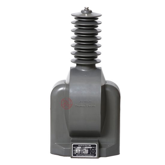
JDZW-35 33kV Cast-Resin Voltage Transformer for Substation Metering and Protection – IEC 61869-3 Certified
Introduction to the JDZW-35 Voltage Transformer
The JDZW-35 is a single-phase, outdoor-rated, cast-resin insulated voltage transformer (VT) engineered for precise voltage measurement and reliable protective relay operation in 33kV (IEC) / 35kV (domestic) medium-voltage networks. Designed in strict compliance with IEC 61869-3 and GB/T 20840.3, this instrument transformer serves as a critical interface between high-voltage primary circuits and secondary instrumentation, ensuring galvanic isolation while accurately scaling system voltage to standardized secondary levels (typically 100 V or 100/√3 V).
Operating Principle of Cast-Resin Insulation
Cast-resin insulation in the JDZW-35 employs vacuum pressure impregnation (VPI) of cycloaliphatic epoxy resin around the primary and secondary windings and the grain-oriented electrical steel (GOES) core. This monolithic encapsulation eliminates air voids, suppresses partial discharges (<5 pC at rated voltage), and provides superior dielectric strength compared to oil-paper systems. The resin’s high thermal conductivity (≈0.2 W/m·K) enables efficient heat dissipation, supporting continuous operation under load without thermal runaway. Unlike oil-filled units, the solid dielectric is non-flammable, eliminating fire hazards and environmental contamination risks—critical for indoor substations or environmentally sensitive zones.
Advantages Over Oil-Immersed Designs
The JDZW-35’s dry-type construction offers significant operational advantages: zero maintenance of insulating fluid, immunity to oil degradation or leakage, reduced weight (typically 30–40% lighter than equivalent oil units), and faster commissioning due to absence of oil testing or degassing procedures. Its compact footprint facilitates installation in space-constrained switchgear bays. Furthermore, the absence of flammable materials allows deployment in confined urban substations where fire codes prohibit oil-filled equipment. Long-term reliability is enhanced by resistance to moisture ingress—achieved through hermetic sealing of terminals and UV-stabilized resin housing rated for -40°C to +40°C ambient operation.
Typical Applications Overview
This VT is predominantly deployed in 35kV distribution substations for revenue metering (Class 0.2 or 0.5S), protective relaying (Class 3P or 6P), and synchro-check functions. It supports both grounded-wye and open-delta configurations for ground-fault detection. Common installations include utility-owned zone substations, industrial plant switchyards (e.g., cement, mining, or petrochemical facilities), and renewable energy interconnection points (solar farms, wind parks) where accurate voltage monitoring is essential for grid compliance. The unit’s robust design withstands transient overvoltages from switching surges or lightning, ensuring uninterrupted secondary signal integrity during fault conditions.
Technical Specifications
The JDZW-35 is engineered to deliver precision and durability under demanding service conditions. All parameters adhere to IEC 61869-3 tolerance limits and are validated through type, routine, and special tests per manufacturer protocols.
Rated Electrical Parameters
| Parameter | Value |
|---|---|
| System Voltage (IEC) | 33 kV |
| System Voltage (Domestic) | 35 kV |
| Rated Primary Voltage | 35,000 / √3 V (for wye-connected systems) |
| Rated Secondary Voltage | 100 / √3 V (metering) or 100 V (protection) |
| Voltage Ratio | 35,000/√3 : 100/√3 V (i.e., 350:1) |
| Accuracy Class (Metering) | 0.2, 0.5, 0.5S |
| Accuracy Class (Protection) | 3P, 6P |
| Rated Output (per burden class) | 10–100 VA (e.g., 30 VA @ 0.2 class; 50 VA @ 3P class) |
| Insulation Level (LI/AC) | 170 kV / 70 kV (per IEC 60071-1) |
| Short-Time Withstand Current | Not applicable (VTs are not designed for fault current conduction) |
| Frequency | 50 Hz ±0.5 Hz |
Standard Service Conditions
The JDZW-35 operates reliably under the following environmental parameters: ambient temperature range of -40°C to +40°C, relative humidity up to 100% (condensing permitted), and installation altitude ≤1,000 m above sea level. For altitudes exceeding 1,000 m, dielectric strength must be derated by 1% per 100 m increment above baseline. The unit is rated for outdoor use with IP54 protection against dust and water ingress. Pollution severity is classified as Medium (creepage distance ≥25 mm/kV RMS phase-to-ground). Thermal stability is maintained up to 120% of rated voltage continuously, with short-term overvoltage capability of 190% for 30 seconds (per IEC 61869-3 Section 5.3).
Burden and Accuracy Compliance
Accuracy classes are guaranteed only when connected to burdens within specified limits. For example, a 0.2-class winding must operate between 25% and 100% of its rated VA (e.g., 7.5–30 VA for a 30 VA rating). Phase error must not exceed ±10 minutes, and voltage error ≤±0.2% at rated burden and power factor of 0.8 lagging. Protection-class windings (3P/6P) maintain composite error ≤3% or 6% respectively under specified fault conditions (e.g., 5× rated voltage for 30 s). Burden impedance must be purely resistive-inductive; capacitive burdens can induce ferroresonance and are strictly prohibited without damping circuits.
Typical Applications
The JDZW-35’s versatility makes it suitable across diverse power infrastructure segments requiring accurate, isolated voltage signals.
Substation Secondary Metering
In utility-owned 35kV/10kV distribution substations, the JDZW-35 provides the voltage input for revenue-grade kWh meters (Class 0.5S). Its low phase displacement ensures minimal billing error over time—critical for regulatory compliance. The transformer is typically installed on the high-voltage busbar, with secondary leads routed to a metering cabinet via shielded twisted-pair cable to mitigate electromagnetic interference. Redundant VTs may be used for dual-metering setups, with one dedicated to billing and another to SCADA telemetry.
Industrial Power Distribution
Heavy industries (e.g., steel mills, chemical plants) deploy JDZW-35 units to monitor process voltage stability and feed protective relays for motor control centers or capacitor banks. In arc-furnace environments with high harmonic distortion, the GOES core’s low hysteresis loss minimizes heating under non-sinusoidal waveforms. The VT’s robust insulation withstands frequent switching transients from large inductive loads. Secondary outputs often interface with digital multifunction relays (e.g., SEL-351) for over/under-voltage, loss-of-potential, and vector shift protection schemes.
Renewable Energy Integration
Solar photovoltaic (PV) farms connecting to 35kV grids use JDZW-35 transformers for grid synchronization and anti-islanding protection. During cloud transients, rapid voltage fluctuations require VTs with excellent dynamic response—achieved here via low leakage reactance (<2% at rated current). The unit also supplies voltage data to SCADA systems for reactive power control (Q(V) droop), ensuring compliance with grid codes like GB/T 19964. Its maintenance-free design reduces O&M costs in remote solar sites where access is limited.
Rural and Suburban Distribution Networks
In rural electrification projects, JDZW-35 VTs enable cost-effective voltage monitoring on long radial feeders prone to voltage drop. Mounted on pole-top platforms or pad-mounted switchgear, they support automatic voltage regulators (AVRs) and capacitor bank controllers. The cast-resin housing resists UV degradation and salt fog in coastal areas, while the absence of oil eliminates theft or spill risks in unsecured locations. Secondary outputs often feed RTUs for remote voltage profiling, aiding in network optimization.
Ground-Fault Detection Systems
When configured in open-delta (broken-delta) arrangement across three phases, the JDZW-35 detects zero-sequence voltage during ground faults. The residual voltage output (typically 100 V at full ground fault) triggers ground-fault relays (e.g., 59N). This application demands high accuracy under unbalanced conditions—ensured by matched phase characteristics (ratio error variation <0.1% between units). Damping resistors are often installed across the open delta to prevent ferroresonance during single-phase switching.
Compliance with International Standards
The JDZW-35’s design, testing, and performance are governed by harmonized international and Chinese national standards, ensuring global interoperability and safety.
IEC 61869-3 Certification Details
IEC 61869-3 specifies requirements for inductive voltage transformers, covering insulation coordination, accuracy, temperature rise, and short-circuit behavior. The JDZW-35 meets all mandatory clauses: power frequency withstand voltage (70 kV RMS for 1 min), lightning impulse withstand (170 kV peak), partial discharge inception voltage (>1.2 × Um/√3), and temperature rise limits (<60 K for windings at 1.2 × rated voltage). Type tests—including capacitance and dissipation factor measurements—are performed at accredited laboratories, with certificates available upon request. The standard mandates that accuracy be verified at 80%, 100%, and 120% of rated voltage.
Alignment with GB/T 20840.3
GB/T 20840.3 is China’s national adoption of IEC 61869-3, with minor deviations reflecting local grid practices. Key differences include: (1) domestic systems reference 35kV nominal voltage vs. IEC’s 33kV; (2) creepage distance requirements are stricter in polluted regions (≥31 mm/kV for heavy pollution); and (3) acceptance criteria for ratio error may be tighter for Class 0.2S (±0.15% vs. IEC’s ±0.2%). The JDZW-35 is dual-certified, bearing both CQC (China Quality Certification) and international marks (e.g., CE), facilitating deployment in export projects and domestic infrastructure alike.
Testing and Certification Protocols
Each production batch undergoes routine tests per IEC 61869-3 Annex B: visual inspection, winding resistance measurement, polarity verification, turns ratio check (±0.25% tolerance), and power frequency withstand. Type tests—conducted every five years or after design changes—include temperature rise, short-circuit withstand (for CTs; not applicable to VTs), and seismic qualification (if required). Special tests like chopped impulse or wet AC withstand may be requested for harsh environments. Full test reports comply with ISO/IEC 17025 and are traceable to national metrology institutes.
On-Site Testing Procedures
Field commissioning requires verification of key parameters to ensure safe integration into the power system.
Insulation Resistance Test
Using a 2,500 V DC megohmmeter, measure insulation resistance between primary-to-secondary, primary-to-ground, and secondary-to-ground. Acceptance criteria: >10,000 MΩ at 20°C. Values below 1,000 MΩ indicate moisture ingress or resin cracking. Temperature correction is applied using R20 = Rt × 2(t-20)/10. This test must precede any high-voltage energization.
Turns Ratio Test
Apply 100–500 V AC to the primary and measure secondary voltage with a calibrated voltmeter (accuracy class 0.1). Calculate actual ratio and compare to nameplate. Tolerance: ±0.25% for metering classes, ±0.5% for protection classes. Deviations beyond tolerance suggest winding shorts or incorrect tap selection. Automated ratio testers (e.g., Omicron CT Analyzer) provide phase angle data simultaneously.
Polarity Test
Verify reducing polarity using the DC kick method: momentarily connect a 6–12 V battery across primary terminals (H1+, H2–). A DC milliammeter on the secondary (X1+, X2–) should show a positive deflection on make and negative on break. Incorrect polarity compromises wattmeter and relay operation, leading to false tripping or billing errors.
Power Frequency Withstand Voltage Test
Apply 70 kV RMS (50 Hz) between primary and grounded secondary/enclosure for 1 minute. Leakage current must remain <1 mA. This validates insulation integrity post-transportation. Use a calibrated test transformer with overcurrent trip set at 5 mA. Never perform this test if insulation resistance is marginal.
Open-Circuit Characteristic Test
Gradually increase primary voltage from 0 to 150% of rated (52.5 kV) while measuring secondary voltage and excitation current. Plot Vsec vs. Iexc. Knee-point voltage should exceed 120% of rated secondary (120 V). Excessive excitation current (>10% of rated secondary current at 100 V) indicates core saturation or turn-to-turn faults. This test is critical for ferroresonance assessment.
Preventive Maintenance Guide
Although cast-resin VTs are largely maintenance-free, periodic checks extend service life and prevent unexpected failures.
Annual Visual and Electrical Inspection
Inspect for surface tracking, cracks, or discoloration on the resin housing. Check terminal tightness (torque: 15 N·m for M10 bolts) and corrosion on grounding lugs. Perform insulation resistance and ratio tests annually. Clean housing with mild detergent if salt or dust deposits accumulate—never use solvents that degrade epoxy. Verify secondary wiring integrity, especially in outdoor cabinets exposed to thermal cycling.
Five-Year Comprehensive Maintenance
Every 60 months, conduct partial discharge measurement using HFCT sensors (<10 pC acceptable). Re-calibrate secondary outputs against a reference standard. Inspect mounting hardware for fatigue, particularly in seismic zones. Review historical test data for trends: a 20% drop in insulation resistance or 0.1% increase in ratio error warrants further investigation. Replace surge arresters connected to the VT if their leakage current exceeds 0.5 mA.
Fault Diagnosis and Troubleshooting
Common failure modes include: (1) secondary open-circuit—causes dangerous overvoltage on primary; always short secondary before disconnecting; (2) core saturation—indicated by overheating or distorted waveform; (3) moisture ingress—evidenced by low IR and high tan δ. If secondary voltage reads zero, check fuses (typically 1–2 A, fast-acting) and wiring continuity. Persistent ratio errors may require factory recalibration or replacement.
Conclusion
The JDZW-35 cast-resin voltage transformer represents a technically mature solution for 33kV/35kV applications demanding precision, safety, and longevity. Its epoxy-encapsulated design eliminates the operational liabilities of oil-filled alternatives while delivering IEC 61869-3-compliant accuracy across metering (0.2/0.5S) and protection (3P/6P) functions. The use of GOES core material ensures low losses and stable performance under harmonic distortion, critical for modern grids integrating renewables. Rigorous adherence to both international (IEC) and Chinese (GB) standards guarantees interoperability and regulatory acceptance worldwide. With a design life of 25–30 years under standard service conditions, the JDZW-35 minimizes lifecycle costs through zero fluid maintenance, resistance to environmental stressors, and robust transient withstand capability. When installed and tested per recommended procedures, it provides decades of reliable voltage transformation—forming the backbone of accurate energy accounting and dependable system protection in medium-voltage infrastructure. Engineers specifying this unit can be confident in its technical pedigree, certification validity, and field-proven resilience across industrial, utility, and renewable energy sectors.