Product Overview
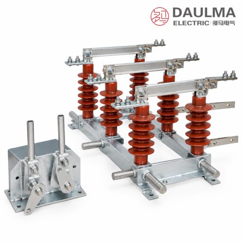
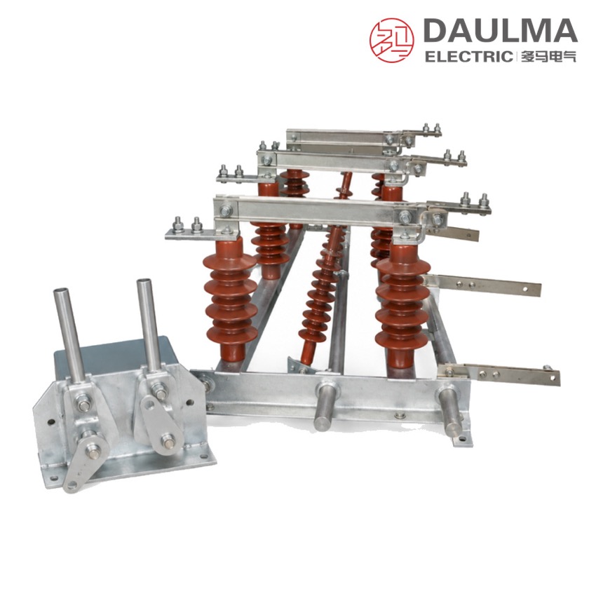
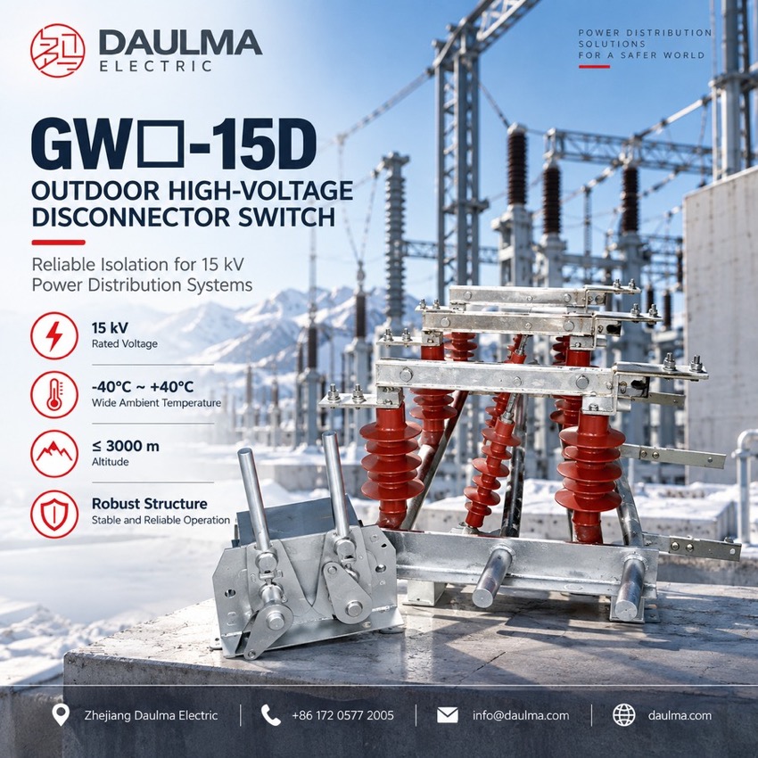
The GW□-15D is a single-pole outdoor high-voltage disconnector for opening and closing no-load circuits in 15 kV and 40.5 kV networks. Used together with circuit breakers, it provides a clearly visible insulating gap for the safe isolation of lines and equipment. On the earthing-switch (D) version the earthing knife is operated through the CS6 manual mechanism with a mechanical interlock that blocks misoperation, so portable earth leads are not needed. Three poles assemble side by side on a common galvanised base frame, and a pollution-proof version is available for heavily polluted areas.
Product Display
Model Designation
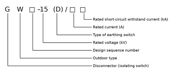
Model format: G W□-15 (D)/□□
- G — disconnector
- W — place of use: outdoor
- □ — design sequence number
- 15 — rated voltage, kV
- (D) — with earthing switch (omitted for the plain version)
- □□ — rated current, A, and rated short-circuit withstand current, kA
Service Conditions
- Altitude: not above 3000 m
- Ambient temperature: upper limit +40 ℃, lower limit −10 ℃ for general areas (−40 ℃ for cold areas)
- Wind pressure: not exceeding force 8
- Seismic intensity: not above intensity 8
- No frequent violent vibration at the installation site
- Standard type: site free from gases, vapours, chemical deposits, salt mist, dust or other explosive or corrosive substances that seriously affect insulation and conductivity
- Pollution-proof type: suitable for heavily polluted areas, free from substances that may cause fire or explosion
Construction
Each pole is an independent single-pole unit carrying the knife, moving and static contacts, operating insulator and supporting porcelain insulators on a galvanised steel base; three poles are assembled side by side on the common mounting frame to form the three-phase set. A three-phase linkage shaft and bent arms drive all poles from one CS6 manual mechanism, and the side or centre operating bent arm with the pipe transmission arrangement lets the mechanism sit at a convenient height on the structure.
On the earthing-switch (D) version the earthing knife is driven through its own tie rods, and the mechanical interlock between main and earth contacts enforces the correct operating sequence, replacing portable earth leads during maintenance. For remote operation a motorised mechanism can be coupled through the three-phase linkage shaft, bent arms and pipe transmission with open / close position indication, and the pollution-proof version uses extended-creepage insulators for heavily polluted coastal and industrial areas.
Technical Data
| Item | Value | Remark |
|---|---|---|
| Rated voltage | 15 / 40.5 kV | Series designation covers both classes |
| Rated current | Fixed by technical agreement | The catalogue does not tabulate current ratings for this series |
| Rated short-circuit withstand current | Fixed by technical agreement | Final parameters follow the nameplate and shipped documents |
| Earthing switch (D version) | Earthing knife with mechanical interlock | Driven through its own tie rods from the CS6 mechanism |
| Operating mechanism | CS6 manual; motorised optional | Three-phase linkage, side or centre operating bent arm |
| Pollution-proof version | Extended-creepage insulators | For heavily polluted areas |
| Phase arrangement | Single poles on common galvanised frame | Three poles assembled side by side form the three-phase set |
Standards
The source catalogue for the GW□-15D series names no specific product standard and does not tabulate rated current or withstand ratings. All rating data are fixed by the technical agreement at order, and final parameters follow the nameplate and shipped documents; the disconnector is used in combination with a circuit breaker with which it must be electrically or mechanically interlocked.
Installation & Dimensions
Installation Diagram
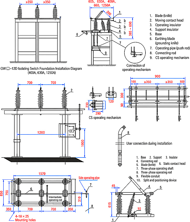
Assemble the single poles on the mounting frame at their phase spacing, fix the frame through the 4 × 18 × 25 mm mounting holes and earth it reliably. Fit the three-phase linkage shaft, bent arms and tie rods, connect the CS6 mechanism at the side or centre operating position (mechanism mounting height 1200 / 1000 mm), and check the interlock between the main and earthing switches before commissioning.
| Outline dimension | Value (mm) |
|---|---|
| Base frame length over mounting holes | 1570 |
| Phase spacing | 700 + 700 |
| Upper frame width | 900 |
| Terminal spacing at live parts | ≥ 350 |
| Pole centre height | 850 / 750 |
| Single-pole insulator height | 615 |
| Mechanism mounting height | 1200 / 1000 |
| Side operating bent arm clearance | 310 |
| Mounting holes | 4 × 18 × 25 |