Product Overview
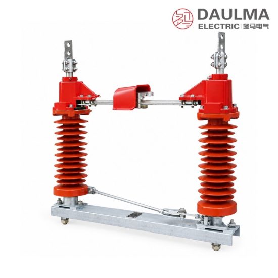
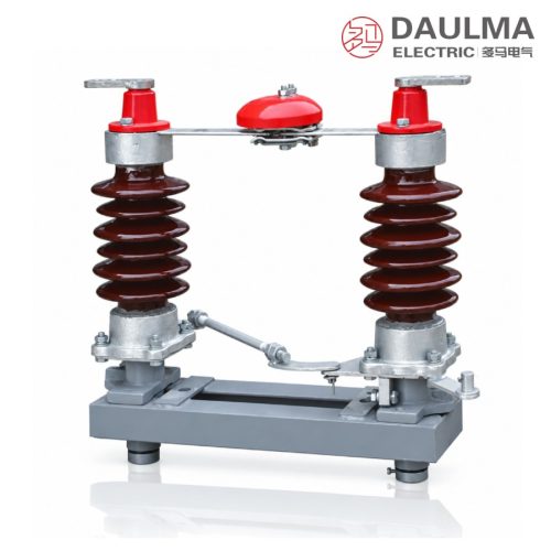
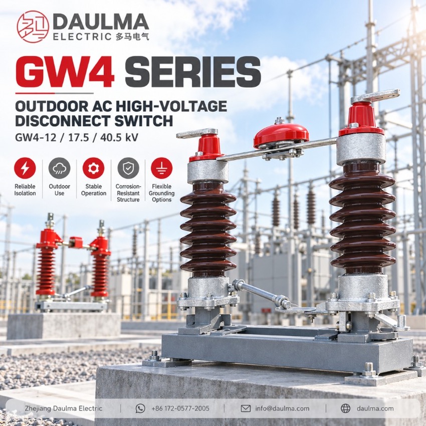
The GW4 is a double-post, horizontal-rotation outdoor AC high-voltage disconnector for three-phase 50 Hz networks rated 12, 17.5 and 40.5 kV. It opens and closes lines under voltage but without load, giving a clearly visible insulating break; it cannot break load or short-circuit current. Two support-post insulators per pole rotate the knife contacts through about 90°. Versions come without earthing, with single-side or double-side earthing (D), and a pollution-proof grade II insulator type suits contaminated sites. The series meets GB 1985-89 and IEC 129 / IEC 694.
Product Display
Model Designation
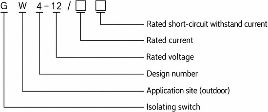
Model format: G W 4-12/□□
- G – disconnector
- W – place of use: outdoor
- 4 – design sequence number
- 12 – rated voltage, kV
- □ – rated current, A
- □ – rated short-circuit withstand current, kA
Service Conditions
- Altitude: 1000 to 3000 m
- Ambient temperature: not above +40 °C and not below -30 °C (-40 °C for cold areas)
- Wind pressure: not above 700 Pa (wind speed about 34 m/s)
- Seismic intensity: not above intensity 8
- Ice thickness: not above 10 mm
- Site free from flammable or explosive hazards, chemical corrosion and violent vibration
- Insulator pollution level: general type grade 0, pollution-proof type grade II
Construction
Each pole carries two support-post insulators that rotate in opposite directions to open or close the knife contacts through about 90°, giving a wide, clearly visible break. The base frame, support insulators, outgoing terminals and self-cleaning finger contacts form the main conducting circuit.
The disconnector is driven by a manual operating mechanism through the three-phase linkage shaft. It is supplied without earthing, with single-side earthing or as the D type with double-side earthing – where fitted the earthing switch is interlocked against the main contacts – and a pollution-proof insulator option (grade II) is available for heavily polluted areas.
Technical Data
| Rated voltage (kV) | Rated current (A) | Rated peak withstand current (kA) | Rated short-time withstand current, 4 s (kA) |
|---|---|---|---|
| 12 | 600 – 630 | 80 | 31.5 |
| 17.5 | 400 – 1000 | 50 | 20 |
| 40.5 | 400 – 1250 | 80 | 31.5 |
| Earthing switch (where fitted) | – | 50 / 80 | 20 / 31.5 |
Standards
The GW4 is designed and tested to GB 1985-89 AC High-Voltage Disconnectors, IEC 129 (1984) AC Disconnectors and Earthing Switches and IEC 694 (1980) Common Specifications for High-Voltage Switchgear and Controlgear.
Installation & Dimensions
Installation Diagram
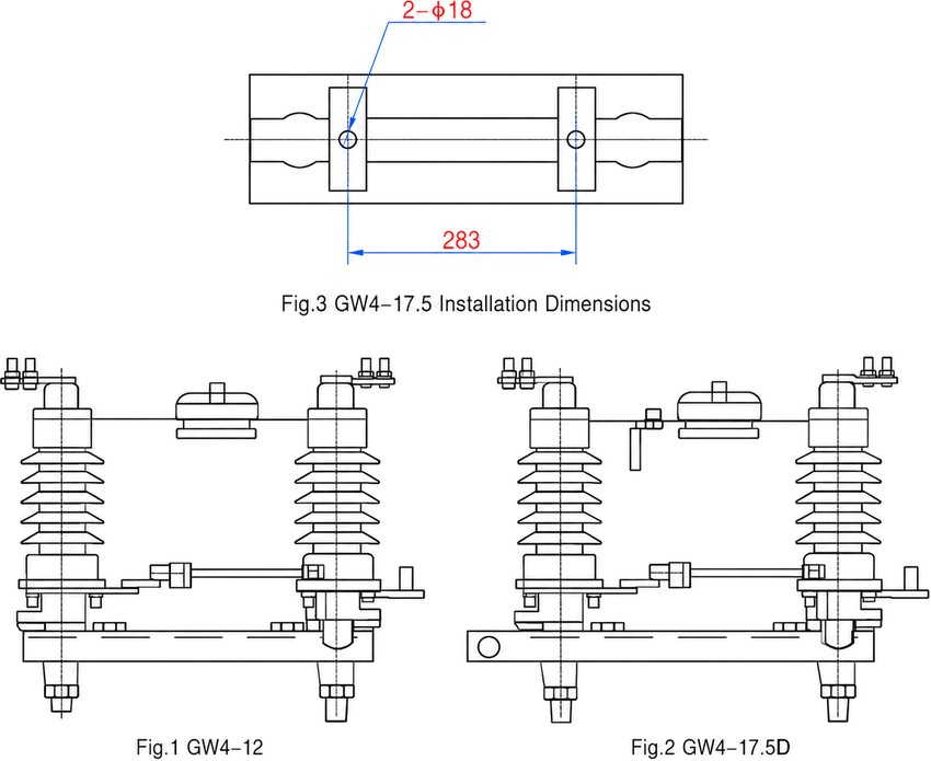
Assemble the double-post poles on the common base frame at the specified phase spacing and fix the frame to the gantry or foundation through the mounting holes – 2 × Φ18 on the GW4-17.5 base at a 283 mm hole pitch. Couple the poles to the manual operating mechanism with the three-phase linkage shaft, verify free travel through about 90°, correct contact seating and the full visible break before energising, and bond the base frame to the earth grid.
| Dimension | Value |
|---|---|
| Mounting holes (GW4-17.5 base) | 2 × Φ18 |
| Mounting hole pitch | 283 mm |
| Knife contact rotation | approx. 90° |