Product Overview
JDZ10-3/6/10B/180 is an indoor epoxy cast-resin voltage transformer designed for medium-voltage switchgear applications. It is suitable for 50Hz / 60Hz AC systems and is used to provide secondary voltage signals for voltage measurement, electric energy metering, voltage monitoring and relay protection.
This model is the same general product family as the JDZX10 compact indoor voltage transformer, but it should be positioned differently. JDZ10-3/6/10B/180 is better described as a compact 180mm cabinet-type VT/PT with simple line-voltage ratios such as 3/0.1, 6/0.1 and 10/0.1. It also supports secondary combinations such as 0.1/0.1kV and 0.1/0.22kV, making it suitable for metering plus auxiliary secondary output requirements.
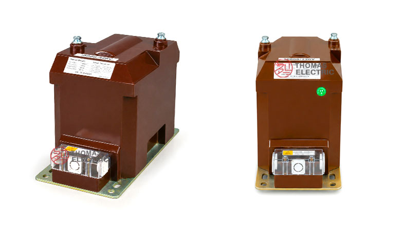
Product Display

Application Position
The JDZ10-3/6/10B/180 transformer is installed inside indoor air-insulated switchgear, metering cabinets or compact medium-voltage panels. The primary side connects to the 3kV, 6kV or 10kV circuit, while the secondary side provides standardized voltage output for meters, relays, control devices and auxiliary circuits.
Main Applications
- Indoor 3kV, 6kV and 10kV medium-voltage switchgear
- 3.6kV, 7.2kV and 12kV class distribution systems
- Voltage measurement and energy metering
- Voltage monitoring and indication circuits
- Relay protection voltage input circuits
- Auxiliary secondary output applications using 0.22kV secondary voltage
- Compact cabinet installations requiring a 180mm structure
Key Specifications
| Item | Specification |
|---|---|
| Model series | JDZ10-3B/180 / JDZ10-6B/180 / JDZ10-10B/180 |
| Product type | Indoor voltage transformer / potential transformer |
| Insulation structure | Indoor epoxy cast-resin insulation |
| Installation | Indoor switchgear installation |
| System voltage | 3kV, 6kV and 10kV systems |
| International voltage class | 3.6kV, 7.2kV and 12kV classes |
| Rated frequency | 50Hz / 60Hz |
| Ambient temperature | -25°C to +40°C |
| Rated insulation level | 3.6/25/40kV, 7.2/30/60kV, 12/42/75kV |
| Secondary configurations | 0.1kV, 0.1/0.1kV and 0.1/0.22kV options |
| Max. output | 600VA, 500VA or 1000VA depending on configuration |
| Approximate weight | 33kg |
| Standards | GB20840.3-2013, IEC61869-3:2011 and project-specific requirements |
Application Fit
Suitable For
- Indoor switchgear requiring compact cast-resin VT installation
- 3kV, 6kV and 10kV medium-voltage systems
- Projects requiring simple line-voltage ratio output such as 6/0.1kV or 10/0.1kV
- Metering circuits using 0.2, 0.5 or 3.0 accuracy classes
- Dual-secondary circuits requiring 0.1/0.1kV output
- Applications requiring 0.22kV auxiliary secondary output
- Cabinet designs where an approximately 180mm wide VT body is suitable
Not Recommended For
- Outdoor exposed installations without enclosure protection
- High-frequency electronic transformer applications
- Oil-immersed voltage transformer applications
- Grounded phase-to-neutral VT schemes requiring 0.1/√3 and 0.1/3 secondary ratios
- Three-phase integrated handcart VT applications
- Applications requiring anti-ferroresonance three-phase design
Installation Conditions
- Installation location: indoor air-insulated switchgear or protected indoor cabinet
- Rated frequency: 50Hz / 60Hz power-frequency AC system
- Ambient temperature: -25°C to +40°C
- Clearance: confirm primary terminal clearance and cabinet insulation distance before installation
- Terminal access: secondary terminal box should remain accessible for wiring, testing and maintenance
- Maintenance: clean the resin surface and inspect terminal fastening during routine service
Technical Structure
The JDZ10-3/6/10B/180 series uses an epoxy resin cast body with the primary winding, secondary winding and magnetic core enclosed in solid insulation. Compared with JDZX grounded-type versions, this product is more focused on line-voltage transformation and practical cabinet secondary output, including 0.1kV and 0.22kV secondary configurations.
| Component | Description |
|---|---|
| Epoxy cast-resin body | Indoor insulation structure with moisture resistance and mechanical protection |
| Primary winding | Designed for 3kV, 6kV or 10kV system voltage according to model selection |
| Metering secondary | Provides 0.1kV secondary voltage for meters and measurement instruments |
| Dual-secondary option | Provides 0.1/0.1kV output for separated measurement and monitoring circuits |
| Auxiliary output option | Provides 0.22kV secondary voltage where the project requires auxiliary output |
| Secondary terminal box | Front terminal area for wiring, testing and identification |
| Mounting base | Metal base for compact switchgear installation |
Model Designation

- J = Voltage transformer
- D = Single-phase voltage transformer structure
- Z = Epoxy cast-resin insulation
- 10 = Design sequence or product series code
- 3 / 6 / 10 = Rated system voltage code for 3kV, 6kV or 10kV applications
- B = Structure or configuration code, subject to approved drawing and nameplate
- 180 = Compact structure / outline size code
Technical Data
The following data is reorganized from the JDZ10-3/6/10B/180 product sample. For international product pages, the 3kV, 6kV and 10kV ratings should be expressed with their corresponding 3.6kV, 7.2kV and 12kV insulation classes.
| Model | Rated
Voltage Ratio |
Accuracy Class /
Rated Output |
Max.
Output |
Rated I
nsulation Level |
|---|---|---|---|---|
| JDZ10-3B/180 | 3 / 0.1kV | 0.2 — 30VA 0.5 — 75VA 1.0 — 150VA 3.0 — 300VA |
600VA | 3.6/25/40kV |
| JDZ10-6B/180 | 6 / 0.1kV | 7.2/30/60kV | ||
| JDZ10-10B/180 | 10 / 0.1kV | 12/42/75kV | ||
| JDZ10-3B/180 | 3 / 0.1 / 0.1kV | 0.2 / 0.2 — 15 / 15VA 0.2 / 0.5 — 15 / 15VA |
500VA | 3.6/25/40kV |
| JDZ10-6B/180 | 6 / 0.1 / 0.1kV | 7.2/30/60kV | ||
| JDZ10-10B/180 | 10 / 0.1 / 0.1kV | 12/42/75kV | ||
| JDZ10-3B/180 | 3 / 0.1 / 0.22kV | 0.2 / 3.0 — 30 / 800VA 0.5 / 3.0 — 75 / 800VA |
1000VA | 3.6/25/40kV |
| JDZ10-6B/180 | 6 / 0.1 / 0.22kV | 7.2/30/60kV | ||
| JDZ10-10B/180 | 10 / 0.1 / 0.22kV | 12/42/75kV |
Technical notes:
- One transformer is supplied with one selected accuracy class and corresponding rated output combination.
- The 0.1kV output is normally used for metering, voltage indication and monitoring.
- The 0.1/0.1kV version can separate measurement and monitoring secondary circuits.
- The 0.22kV secondary output can be used where auxiliary voltage output is required by the cabinet design.
- The 0.22kV configuration has a higher max. output rating of 1000VA in the sample table.
Installation and Dimensions

Dimension Reference
| Item | Reference Value |
|---|---|
| Overall base length | 370 ±2mm |
| Main mounting length | 310mm reference |
| Body length reference | 270mm |
| Base width | 180 ±1mm |
| Overall height | 265 ±5mm |
| Body height reference | 241mm |
| Top terminal spacing | 113.1mm reference |
| Primary terminal bolt | 2-M8 reference |
| Grounding bolt | M8 reference |
| Approximate weight | 33kg |
Terminal and Wiring

- The sample wiring diagrams show single-secondary and dual-secondary arrangements.
- Primary terminals are identified as A and B according to the drawing.
- Secondary terminals may be marked as a, b, 1a, 1b, 2a and 2b depending on configuration.
- For dual-secondary models, confirm which secondary is used for metering and which is used for monitoring or auxiliary output.
- Terminal polarity, grounding and cabinet clearance must be checked before commissioning.
Compliance and Testing
The product information references GB20840.3-2013 and IEC61869-3:2011. For export projects, the final standard reference should be aligned with the buyer’s technical specification, applicable grid requirements and approved test plan.
Typical Routine Tests
- Visual inspection and nameplate verification
- Ratio verification
- Polarity and terminal marking check
- Accuracy test at specified rated burden
- Power-frequency withstand voltage test
- Induced withstand voltage test where applicable
- Insulation resistance test
- Secondary terminal and grounding inspection
- Auxiliary secondary output verification when supplied
Engineering Notes
- Use JDZ10-3B/180 for 3kV systems, JDZ10-6B/180 for 6kV systems and JDZ10-10B/180 for 10kV systems.
- For export pages, write the voltage classes as 3.6kV, 7.2kV and 12kV according to insulation level.
- This model is better for line-voltage secondary output such as 6/0.1kV or 10/0.1kV.
- Use JDZX grounded-type products when the project requires 0.1/√3 and residual 0.1/3 ratios.
- Confirm whether the project requires 0.1kV, 0.1/0.1kV or 0.1/0.22kV secondary output before selection.
- Do not describe this product as a high-frequency transformer; it is a 50Hz / 60Hz power-frequency VT/PT.
Selection Guide
Select by voltage class: Choose JDZ10-3B/180 for 3kV systems, JDZ10-6B/180 for 6kV systems and JDZ10-10B/180 for 10kV systems. Use 3.6kV, 7.2kV and 12kV class wording for international pages.
Select by secondary output: Choose 0.1kV output for standard metering and monitoring. Choose 0.1/0.1kV when two low-voltage secondary circuits are required. Choose 0.1/0.22kV when the panel design requires a 220V auxiliary secondary output.
Select by output burden: Standard single-secondary versions support up to 600VA max. output. Dual 0.1/0.1kV versions support 500VA. The 0.22kV auxiliary output version supports up to 1000VA in the sample data.
Select by cabinet layout: Confirm 370mm base length, 180mm width, 265mm height and secondary terminal position before approving the cabinet structure.
Select by inquiry clarity: A clear inquiry should state model, voltage ratio, secondary output type, accuracy class, rated output, max. output requirement, insulation level and quantity.