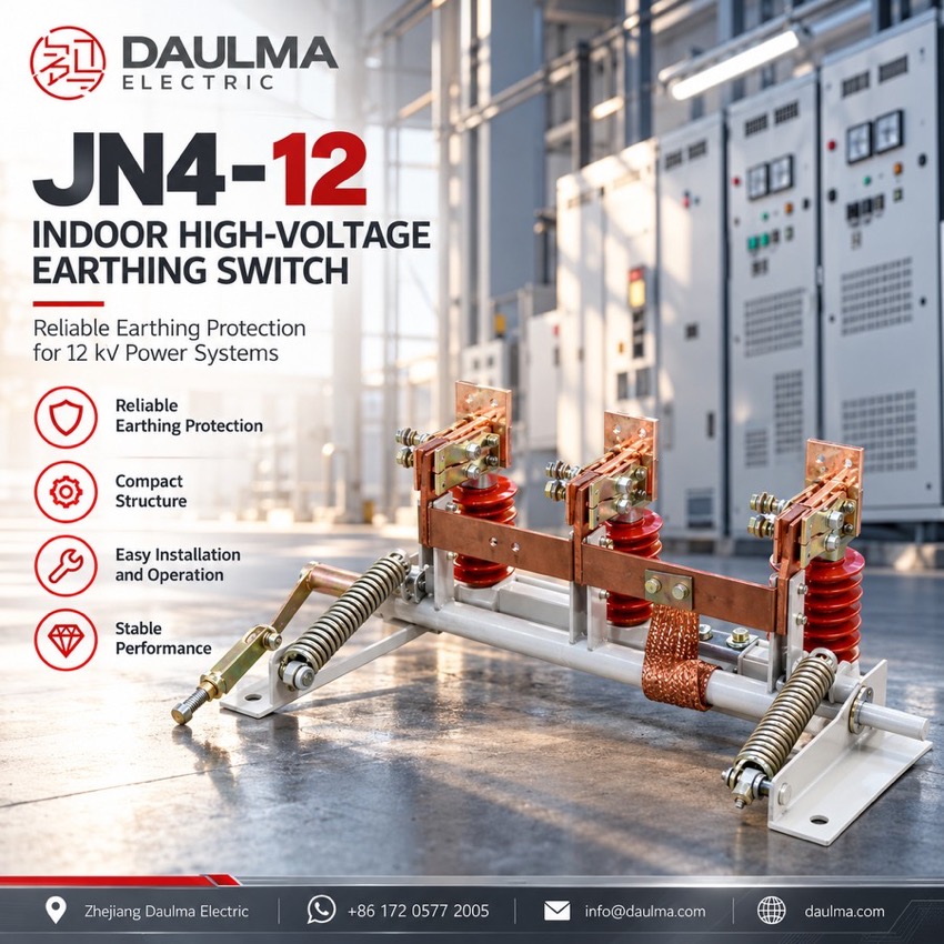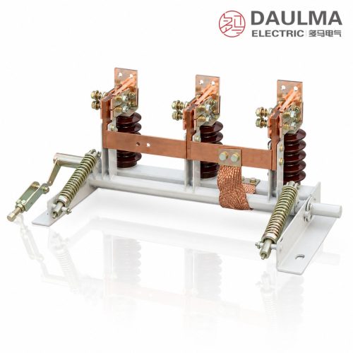
JN4-12 Indoor High-Voltage Earthing Switch, 20 kA - featured

JN4-12KV 20KA Indoor High-Voltage Earthing Switch metal-clad switchgear

JN4-12 Indoor High-Voltage Earthing Switch, 12 kV 20 kA

  • Main earthing component of 12 kV switchgear
  • Carries 20 kA short-time withstand current for 4 s
  • 50 kA peak withstand and short-circuit making
  • Three phase-centre distances, 210 to 250 mm
  • Closes reliably onto a short-circuit current
  • G suffix denotes the plateau, high-altitude type

Product Overview

The JN4-12(G) is an indoor high-voltage earthing switch for 12 kV three-phase 50 Hz systems, the main earthing component of metal-clad withdrawable switchgear, also usable separately. Three earth knives on support insulators over a common frame run from a manual mechanism through one shaft, all poles operating together, interlocked with the associated breaker or cubicle door. It carries 20 kA short-time withstand current for 4 s and closes onto short-circuit current, with 50 kA peak and making ratings; phase-centre distances of 210-250 mm suit different cubicles, and G marks the plateau type.

Product Display
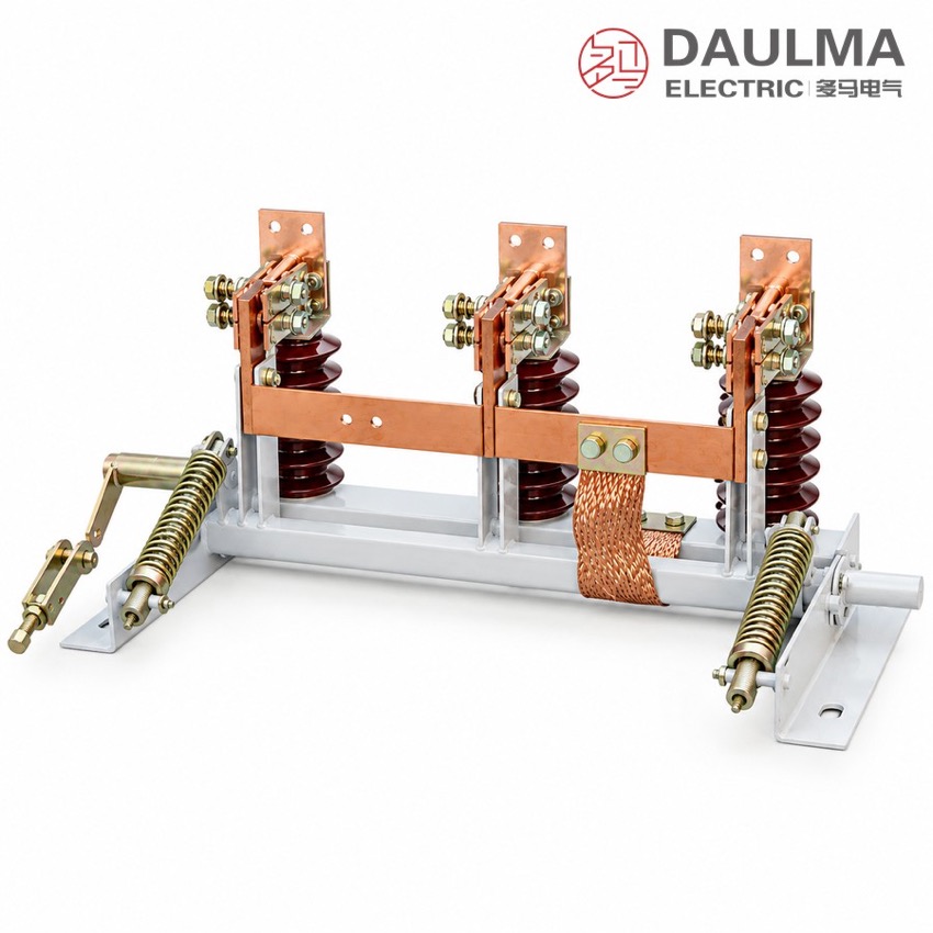
JN4-12 Indoor High-Voltage Earthing Switch, 20 kA - display

JN4-12 Indoor High-Voltage Earthing Switch, 20 kA - poster_display

Model Designation

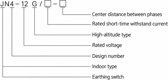
JN4-12 Indoor High-Voltage Earthing Switch, 20 kA - model

Model format: J N 4 – 12 (G) / □ – □

  • J – earthing switch
  • N – place of use: indoor
  • 4 – design sequence number
  • 12 – rated voltage, kV
  • (G) – plateau (high-altitude) type, optional
  • □ – rated short-time withstand current, kA (20)
  • □ – phase-centre (between-pole) distance, mm: 210 / 230 / 250
  • Example: JN4-12G/20-230 is the plateau type at 20 kA with 230 mm pole spacing

Service Conditions

  • Altitude: not above 1000 m
  • Ambient temperature: upper limit +40 °C, lower limit -10 °C
  • Seismic intensity: not above 8 degrees
  • Site free from fire, explosion hazard, severe dust, chemical corrosion and severe vibration

Construction

The JN4-12(G) mounts its three earth knives on support insulators over a common frame, driven through a transmission shaft by a manual operating mechanism so that all three poles make or break the earth connection together. The knives and contacts are designed to close reliably onto a short-circuit current, and the whole assembly is compact, small in size, flexible in operation and easy to install and adjust.

The mechanism can be interlocked with the associated circuit breaker or with the cubicle door to prevent mal-operation. The compact three-pole assembly fits inside metal-enclosed switchgear or can be installed as a separate earthing section, the frame being bonded to the earth network to complete the protective path; the G designation denotes the plateau (high-altitude) version of the same design.

Technical Data

No. Item Unit Data
1 Rated voltage kV 12
2 Rated frequency Hz 50
3 Rated short-time withstand current kA 20
4 Rated short-time withstand duration s 4
5 Rated peak withstand current kA 50
6 Rated short-circuit making current kA 50
7 Phase-centre (between-pole) distance mm 210 / 230 / 250
8 1 min power-frequency withstand voltage kV 42
9 Lightning impulse withstand voltage kV per technical agreement
Selection note: The series carries a single 20 kA / 4 s short-time withstand grade, so select the phase-centre distance of 210, 230 or 250 mm to match the busbar layout of the cubicle. Choose the G plateau version for high-altitude sites above 1000 m, and state the operating-arm position (left or right) and whether a live-display device is required. In metal-clad withdrawable switchgear the JN4-12 is the main earthing component; elsewhere it can be ordered as a separate earthing section with its mechanism interlocked against the associated breaker.

Standards

The source datasheet names no specific product standard for the JN4-12; the ratings follow the order technical agreement and the nameplate of the delivered switch. Values are taken from the type datasheet, in which only the lightning impulse withstand voltage is left open as per technical agreement, together with any special service conditions.

Technical note: Catalogue outline dimensions are for cubicle preparation only; confirm the certified dimensional drawing for the ordered phase-centre distance before installation. Where a value is fixed by the order, in particular the lightning impulse withstand level, the technical agreement and the nameplate of the delivered switch govern over the catalogue page.

Installation & Dimensions

Installation Diagram
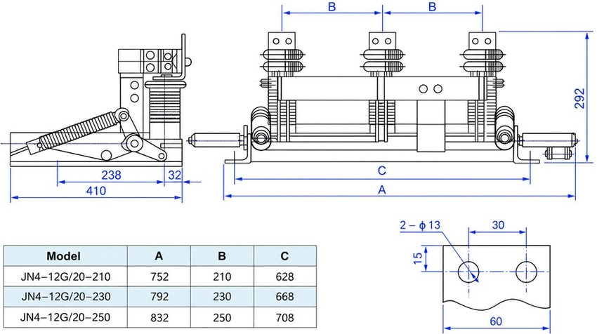
JN4-12 Indoor High-Voltage Earthing Switch, 20 kA - installation

Fix the earthing-switch frame to the cubicle mounting plane through the 2 x Ø 13 holes at the selected phase-centre distance, keeping the earth knives and contacts clear of obstructions. Couple the three poles to the manual operating mechanism through the transmission shaft. Before energising, verify simultaneous and full contact seating of all three poles, correct interlock action with the associated circuit breaker or cubicle door, and reliable bonding of the frame to the earth network.

Model A (mm) B (mm) C (mm)
JN4-12G/20-210 752 210 628
JN4-12G/20-230 792 230 668
JN4-12G/20-250 832 250 708
Safety notice: An earthing switch may only be closed onto a circuit that has been isolated and proved de-energised. The JN4-12 is interlocked with the associated circuit breaker or disconnector so that it cannot be closed onto a live circuit, and the circuit cannot be re-energised while the earth knives remain closed. It carries and makes short-time current but breaks no load; keep the interlocks in service and let qualified personnel operate and maintain the switch with the frame bonded to the earth network.

FAQs

J stands for the earthing switch and N for the indoor place of use, 4 is the design sequence number and 12 the rated voltage in kV. G denotes the plateau (high-altitude) version, and the trailing figures give the rated short-time withstand current in kA and the phase-centre distance in mm, as in JN4-12G/20-230.

It is a main earthing component of 12 kV metal-clad withdrawable switchgear and other indoor high-voltage equipment, and may also be installed separately as an earthing section. Under voltage but without load it earths the de-energised circuit so maintenance work is safe.

Rated voltage 12 kV at 50 Hz, rated short-time withstand current 20 kA for 4 s, rated peak withstand current 50 kA and rated short-circuit making current 50 kA. The 1 min power-frequency withstand voltage is 42 kV and the lightning impulse level follows the technical agreement.

Yes. With a rated short-circuit making current of 50 kA the knives and contacts close reliably onto a short-circuit current. For normal switching it is still operated only under voltage but without load, and it interrupts no current once closed.

Three frames are offered with pole spacings of 210, 230 and 250 mm, modelled JN4-12G/20-210, -230 and -250. The overall dimension A is 752, 792 and 832 mm respectively, and the frame is fixed through 2 x Ø 13 mounting holes.

State the full model, rated voltage, short-time withstand current, phase-centre distance, the operating-arm position (left or right) and whether a live-display device is required. Service conditions are altitude up to 1000 m, ambient air from -10 °C to +40 °C, seismic intensity not above 8, and a site free from fire, explosion hazard, severe dust, chemical corrosion and severe vibration.

Inquiry for JN4-12KV 20KA Indoor High-Voltage Earthing Switch metal-clad switchgear:

Send your project requirements. Our team will reply with technical details and quotation.

Fast response Technical support OEM / ODM