Product Overview
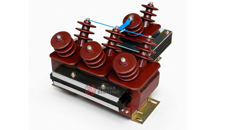
The JSZGF-12 typeface three-phase anti-ferroresonance voltage transformer is an indoor epoxy cast-resin voltage transformer designed for 3.6kV, 7.2kV and 12kV medium-voltage switchgear. It provides standardized secondary voltage signals for voltage metering, residual-voltage monitoring, grounding fault detection and relay protection.
This product was developed to reduce the risk of voltage transformer damage caused by ferroresonance under different system grounding conditions. It uses a semi-enclosed epoxy cast-resin structure with a fully insulated primary winding, and it is suitable for long-term operation under single-phase grounding conditions without abnormal temperature rise when applied according to the specified system design.

Application Position
The JSZGF-12 voltage transformer is normally installed in the voltage transformer compartment of indoor medium-voltage switchgear. It connects to metering instruments, protection relays, grounding fault monitoring devices and control systems through its secondary winding groups.
Main Applications
- 3.6kV, 7.2kV and 12kV indoor medium-voltage switchgear
- Three-phase voltage measurement and voltage monitoring circuits
- Residual-voltage and grounding fault detection circuits
- Relay protection voltage input circuits
- Power metering and monitoring systems
- Medium-voltage networks requiring anti-ferroresonance voltage transformer design
Key Specifications
| Item | Specification |
|---|---|
| Model series | JSZGF-3 / JSZGF-6 / JSZGF-12 |
| Product type | Typeface three-phase anti-ferroresonance voltage transformer |
| Insulation structure | Indoor semi-enclosed epoxy cast-resin insulation |
| Installation | Indoor switchgear installation |
| Rated voltage class | 3.6kV, 7.2kV and 12kV |
| Rated frequency | 50Hz or 60Hz |
| Ambient temperature | -25°C to +40°C |
| Primary winding | Fully insulated primary winding |
| Secondary winding configuration | One secondary winding group or two secondary winding groups according to model |
| Accuracy class | 0.2, 0.5, 1, 3P, 6P and combined metering/protection configurations |
| Limit output | 500VA or 600VA according to winding configuration |
| Standards | GB20840.3-2013, IEC61869-3:2011 and project-specific requirements |
Application Fit
Suitable For
- Indoor medium-voltage switchgear rated 3.6kV, 7.2kV or 12kV
- Systems requiring three-phase voltage measurement and residual-voltage output
- Grounding fault detection circuits in medium-voltage distribution systems
- Relay protection circuits requiring stable voltage reference signals
- Applications where anti-ferroresonance performance is required to reduce VT burnout risk
Not Recommended For
- Outdoor exposed installation without a suitable enclosure
- Low-voltage systems outside the medium-voltage design range
- Applications requiring oil-immersed voltage transformer construction
- Special voltage ratios, secondary winding arrangements or accuracy classes without technical confirmation
Model Comparison
| Model | Voltage Class | Typical Use | Selection Note |
|---|---|---|---|
| JSZGF-3 | 3.6kV | Three-phase voltage metering and residual-voltage protection | Select for 3.6kV switchgear with 3.6/25/40kV insulation level |
| JSZGF-6 | 7.2kV | 7.2kV switchgear voltage monitoring and grounding fault detection | Select according to single or dual secondary winding requirement |
| JSZGF-12 | 12kV | 12kV switchgear metering, monitoring and protection | Select according to 12/42/75kV insulation level and secondary output configuration |
Technical Structure
| Component | Description |
|---|---|
| Core system | Composed of single-phase two-column and three-phase three-column laminated cores |
| Core material | High-quality cold-rolled silicon steel sheet |
| Primary winding | Fully insulated primary winding cast with epoxy resin |
| Secondary winding | Secondary winding groups for metering, residual-voltage output and protection circuits |
| Insulation body | Semi-enclosed epoxy cast-resin structure for indoor medium-voltage use |
| Anti-ferroresonance design | Neutral-point damping / harmonic elimination design to reduce ferroresonance risk |
| Mounting base | Base-mounted structure for indoor switchgear installation |
Model Designation
The JSZGF model code can be interpreted as follows:
| Code | Meaning |
|---|---|
| J | Voltage transformer |
| S | Three-phase structure |
| Z | Epoxy cast-resin insulation |
| G | Anti-ferroresonance / special grounding-related design code |
| F | Typeface / product structure code |
| 3 / 6 / 12 | Model voltage code corresponding to 3.6kV, 7.2kV and 12kV classes |
Technical Data
The following technical data is based on the JSZGF-3, JSZGF-6 and JSZGF-12 product sample. The page uses international medium-voltage class expression for export applications. Voltage ratio values are retained according to the actual primary and secondary winding ratings.
General Technical Conditions
| Item | Technical Condition |
|---|---|
| Load power factor | cosφ = 0.8, lagging |
| Surface creepage distance | Complies with pollution class II requirements |
| Product standards | GB/T 20840.1, GB/T 20840.3, GB20840.3-2013 and IEC61869-3:2011 |
| Rated frequency | 50Hz or 60Hz |
| Ambient temperature | -25°C to +40°C |
Electrical Technical Data
| Type | Voltage
Class |
Voltage
Ratio |
Accuracy Class
and Rated Output |
Limit
Output (VA) |
Rated
Insulation Level (kV) |
|---|---|---|---|---|---|
| JSZGF-3 | 3.6kV | 3000/√3 / 100/√3 / 100 | 0.2/6P(3P)—20/100 0.5/6P(3P)—40/100 1/6P(3P)—80/100 |
600 | 3.6/25/40 |
| JSZGF-6 | 7.2kV | 6000/√3 / 100/√3 / 100 | 7.2/30/60 | ||
| JSZGF-12 | 12kV | 10000/√3 / 100/√3 / 100 | 12/42/75 | ||
| JSZGF-6 | 7.2kV | 6000/√3 / 100/√3 / 100/3 | 0.2/0.2/6P(3P)—15/15/100 0.2/0.5/6P(3P)—15/20/100 0.5/0.5/6P(3P)—20/20/100 |
500 | 7.2/30/60 |
| JSZGF-12 | 12kV | 10000/√3 / 100/√3 / 100/3 | 0.2/0.2/6P(3P)—15/15/100 0.2/0.5/6P(3P)—15/20/100 0.5/0.5/6P(3P)—20/20/100 |
12/42/75 | |
| JSZGF-6 | 7.2kV | 6000/√3 / 100/√3 / 220/√3 / 100 | 0.2/3/6P(3P)—15/400/100 0.5/3/6P(3P)—20/400/100 |
7.2/30/60 | |
| JSZGF-12 | 12kV | 10000/√3 / 100/√3 / 220/√3 / 100 | 0.2/3/6P(3P)—15/400/100 0.5/3/6P(3P)—20/400/100 |
12/42/75 |
Technical notes:
- Rated output and its relative accuracy class are supplied as one selected combination only.
- If the required parameters exceed the listed range, they should be confirmed by agreement between manufacturer and purchaser.
- The product can operate long-term at 120% rated voltage according to the provided technical statement.
- When the system has a single-phase grounding fault, the product can withstand the resulting high voltage for long-term operation under specified conditions.
Service Conditions
- Installation: indoor switchgear or protected electrical installation
- Ambient temperature: -30°C to +40°C according to special service requirement; standard sample range -25°C to +40°C
- Altitude: not over 1000m
- Installation location should be free from fire hazard and dangerous explosive conditions.
- Installation location should be free from strong vibration and severe mechanical impact.
- Neutral point should be directly grounded according to the anti-ferroresonance design requirement.
Installation and Dimensions

The JSZGF-12 typeface series should be installed according to the approved outline drawing, wiring diagram and switchgear layout. The product is a three-phase integrated structure with multiple primary bushings, secondary terminal groups and a base-mounted cast-resin body.
Overall Dimension Reference
| Item | Dimension / Specification |
|---|---|
| Main body length | 480 mm |
| Overall length | 567 ±5 mm |
| Body width | 380 mm |
| Mounting reference width | 130 mm |
| Side bushing spacing | 195 mm |
| Overall height | 292 ±5 mm |
| Mounting holes | 8-M8 |
| Approximate weight | 87 kg |
Terminal and Wiring Notes

- Primary terminals and secondary terminals should be connected according to the approved wiring diagram.
- Different wiring diagrams are available for one secondary winding group or two secondary winding groups.
- Residual-voltage and protection secondary circuits should be connected according to the project protection scheme.
- Terminal markings must be verified before commissioning.
- Neutral-point grounding and anti-ferroresonance connection should follow the project wiring diagram.
Compliance and Testing
The JSZGF-12 typeface series is designed for indoor medium-voltage voltage transformer applications. The provided sample refers to GB20840.3-2013 and IEC61869-3:2011, together with customer-specific requirements.
Typical Routine Tests
- Visual inspection and nameplate verification
- Ratio verification
- Polarity and terminal marking check
- Accuracy test at specified rated burden
- Power-frequency withstand voltage test
- Insulation resistance test
- Secondary winding and residual-voltage winding verification
- Neutral-point and anti-ferroresonance connection verification when required
Engineering Notes
- Select JSZGF-3, JSZGF-6 or JSZGF-12 according to the required 3.6kV, 7.2kV or 12kV switchgear class.
- Confirm whether the system requires one secondary winding group or two secondary winding groups.
- Do not exceed the rated output corresponding to the selected accuracy class.
- For grounding fault detection, confirm residual-voltage ratio, protection class and neutral-point grounding method.
- Check the approximate 87 kg weight, mounting length and switchgear space before installation.
- For special ratios, special protection classes or special environmental conditions, technical confirmation is required before ordering.
Selection Guide
How to select the correct JSZGF model
Select JSZGF-3 for 3.6kV switchgear, JSZGF-6 for 7.2kV switchgear and JSZGF-12 for 12kV switchgear. The rated insulation level and voltage ratio should match the switchgear rated voltage and protection scheme.
How to select secondary winding configuration
Use one secondary winding group when one metering or protection output is required. Use two secondary winding groups when metering and protection circuits, or residual-voltage protection functions, need independent outputs.
How to select accuracy class and rated output
Use 0.2 or 0.5 accuracy class for metering circuits. Use 3P or 6P protection classes for relay protection or residual-voltage detection. The rated output should be higher than the total connected secondary burden.
How to confirm anti-ferroresonance requirement
Anti-ferroresonance voltage transformer design is used where the system requires improved resistance to ferroresonance caused by system grounding or switching conditions. Confirm grounding method, residual-voltage protection scheme and neutral-point connection before final selection.
Ordering Information
Please provide the following information when ordering or requesting a quotation:
- Product model: JSZGF-3, JSZGF-6 or JSZGF-12
- Rated voltage ratio and secondary winding configuration
- Rated frequency: 50Hz or 60Hz
- Required accuracy class and rated output
- Residual-voltage or protection winding requirement
- Rated insulation level
- Neutral-point grounding and anti-ferroresonance connection requirement
- Installation dimensions or switchgear layout requirements
- Applicable standard or project specification
- Quantity
- Special requirements for drawings, test reports, certificates, nameplate language, packaging or shipping