Product Overview
The LFDZ2-10 current transformer is an indoor wall-through type epoxy resin cast current transformer designed for 10kV, 11kV and 12kV class medium-voltage AC systems and rated frequency of 50Hz. It is used for current measurement, electric energy metering, and relay protection in medium-voltage switchgear, distribution cabinets, and indoor power distribution systems.
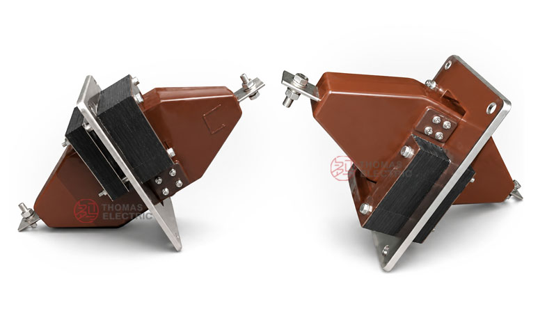
This product adopts a fully enclosed epoxy resin casting structure. The primary winding is a multi-turn through-wall type structure, while the secondary winding and laminated core are encapsulated in the resin body. The mounting plate is clamped on the insulation body, allowing the transformer to be installed vertically or horizontally according to the switchgear layout. The product is suitable for projects requiring wall-through installation, compact structure, stable insulation, and reliable secondary signal output.
Product Type
| Item | Specification |
|---|---|
| Product name | Indoor Wall-Through Epoxy Resin Cast Current Transformer |
| Model series | LFDZ2-10 |
| Product structure | Wall-through type, fully enclosed, epoxy resin cast structure |
| Rated voltage class | 10kV, 11kV and 12kV class medium-voltage AC systems |
| Rated insulation level | 11.5/42/75kV |
| Rated frequency | 50Hz |
| Rated secondary current | 5A |
| Installation direction | Vertical or horizontal installation |
| Typical applications | Current measurement, energy metering, differential protection, relay protection, indoor switchgear |
Product Display


Applications
- 10kV, 11kV and 12kV class systems indoor medium-voltage distribution systems
- Medium-voltage switchgear and distribution cabinets
- Current measurement and electric energy metering circuits
- Relay protection and differential protection circuits
- Wall-through installation where the primary conductor passes through a mounting plate
- Industrial substations, power distribution rooms, and complete electrical equipment
Features
- Wall-through structure: The product is designed for through-wall or through-panel installation in indoor medium-voltage switchgear.
- Epoxy resin casting insulation: The fully enclosed resin body supports stable insulation performance, mechanical strength, and indoor environmental resistance.
- Multi-turn primary winding: The primary winding adopts a multiple winding penetrating structure, suitable for rated primary currents such as 75A to 400A.
- Flexible installation: The product can be fitted vertically or horizontally according to the cabinet structure and busbar arrangement.
- Metering and protection use: Accuracy combinations such as 0.5/0.5, 0.5/D, and D/D are available for measurement and protection requirements.
- Integrated mounting plate: The wall mounting plate is clamped on the insulation body and includes mounting holes for secure installation.
Principle
The LFDZ2-10 current transformer operates according to electromagnetic induction. The primary current flowing through the multi-turn primary winding generates magnetic flux in the laminated core. The secondary winding then outputs a proportional 5A current signal for connected meters, relays, or protection devices. The epoxy resin insulation separates the medium-voltage primary circuit from the secondary measuring circuit and supports reliable indoor operation.
For metering circuits, the transformer provides a proportional current signal for energy measurement. For protection circuits, the selected accuracy combination and protection class shall match the relay setting, burden, and fault-current requirement of the system.
Model Designation

The model code can be interpreted as follows:
| Code | Meaning |
|---|---|
| L | Current transformer |
| F | Wall-through / constructed multi-turn through type |
| Z | Epoxy resin casting insulation |
| D | Differential protection |
| 2 | Design sequence code |
| 10 | Rated voltage class: 10kV |
Technical Data
| Item | Specification |
|---|---|
| Rated voltage | 10kV, 11kV and 12kV class systems |
| Rated insulation level | 11.5/42/75kV |
| Rated frequency | 50Hz |
| Rated primary current | 75A, 100A, 150A, 200A, 300A, 400A |
| Rated secondary current | 5A |
| Accuracy combination | 0.5/0.5, 0.5/D, D/D |
| Power factor of burden | cosφ = 0.8, lagging |
| Structure | Fully enclosed epoxy resin casting with laminated core and secondary winding |
| Installation | Wall-through mounting; vertical or horizontal installation |
| Applicable standard | IEC standard and GB1208-87 current transformer requirements |
Selection Table
The following table provides a compact selection reference for common LFDZ2-10 ratios and accuracy combinations. Long table headers are wrapped into two lines to keep the layout suitable for responsive website pages.
| Rated
Primary Current (A) |
Rated
Secondary Current (A) |
Accuracy
Combination |
Rated
Insulation Level (kV) |
Application
Reference |
|---|---|---|---|---|
| 75 | 5 | 0.5/0.5 0.5/D D/D |
11.5/42/75 | Measurement or protection circuits |
| 100 | Measurement or protection circuits | |||
| 150 | Measurement or protection circuits | |||
| 200 | Measurement or protection circuits | |||
| 300 | Measurement or protection circuits | |||
| 400 | Measurement or protection circuits |
Note: Final rated output, burden, protection accuracy, and test requirements shall be confirmed according to the nameplate, approved drawing, and project technical agreement.
Service Conditions
- Installation location: indoor medium-voltage switchgear
- System voltage: 10kV, 11kV and 12kV class systems
- Rated frequency: 50Hz
- Ambient temperature: normally -5°C to +40°C unless otherwise specified
- The installation environment should be free from severe vibration, corrosive gas, explosive medium, conductive dust, heavy pollution, and abnormal condensation.
- For high altitude, coastal, humid, or heavy-pollution environments, the insulation and installation requirements should be confirmed before ordering.
Standards and Compliance
The LFDZ2-10 current transformer is designed for indoor medium-voltage current transformer applications and can be supplied according to IEC standard and GB1208-87 current transformer requirements. Project-specific requirements such as routine test reports, insulation withstand tests, ratio accuracy tests, polarity verification, and special inspection documents should be confirmed during technical review.
Installation and Dimensions

The LFDZ2-10 current transformer is designed for wall-through mounting. The product includes a mounting plate with four installation holes, and it can be installed vertically or horizontally according to the switchgear layout. Final dimensions, wall-opening size, mounting hole position, and terminal direction should be confirmed with the approved drawing before cabinet production.
Dimensions
| Item | Dimension / Note |
|---|---|
| Mounting hole distance | 160mm × 160mm reference |
| Overall mounting height | 215mm / 275mm reference according to drawing position |
| Window / opening reference | 95mm reference area shown in outline drawing |
| Mounting hole | 4-Φ14 |
| Installation direction | Vertical or horizontal installation |
Unit: mm. Final dimensions are subject to confirmed drawing and selected specification.
Safety Notes
- Confirm the model, current ratio, accuracy combination, insulation level, and burden before installation.
- Check the mounting plate, wall opening, busbar routing, and terminal clearance before cabinet assembly.
- Install the transformer vertically or horizontally according to the approved switchgear layout.
- Connect secondary terminals according to polarity marks and the project wiring diagram.
- The secondary circuit of a current transformer must not be open-circuited when the primary circuit is energized.
- During inspection or relay replacement, short-circuit the CT secondary circuit before disconnecting secondary wiring.
- Installation and maintenance shall be carried out by qualified medium-voltage electrical personnel.
Ordering Info
Please provide the following information when ordering or requesting a quotation:
- Product model: LFDZ2-10
- Rated primary current: 75A, 100A, 150A, 200A, 300A, or 400A
- Rated secondary current: 5A
- Accuracy combination: 0.5/0.5, 0.5/D, or D/D
- Rated burden / output requirement
- Rated insulation level and applicable standard
- Installation direction: vertical or horizontal
- Switchgear layout, wall opening, terminal direction, and drawing requirement
- Quantity, certificates, routine test reports, labeling, and packaging requirements
Selection Guide
- Confirm system voltage: Select LFDZ2-10 for indoor medium-voltage AC systems commonly used in 10kV, 11kV and 12kV class networks.
- Confirm installation type: Use this model when a wall-through or through-panel current transformer structure is required.
- Select current ratio: Choose the primary current according to feeder load, metering range, and protection requirement.
- Confirm accuracy combination: Select 0.5/0.5 for measurement-focused circuits, 0.5/D for combined metering and protection, or D/D for differential protection-related applications.
- Check secondary burden: The connected meter, relay, and secondary cable burden should not exceed the rated output of the selected transformer.
- Verify installation space: Check mounting plate dimensions, wall opening, busbar direction, terminal accessibility, and clearances before switchgear production.