Product Overview
The LZZB9-24/220b/4S current transformer is an indoor epoxy cast-resin instrument transformer for 20kV, 22kV and 24kV medium-voltage switchgear. It is used for current measurement, energy metering, feeder monitoring and relay protection in indoor AC power systems with rated frequency of 50Hz or 60Hz.
This product should not be positioned as a generic 12kV CT or as an outdoor waterproof CT. Its main value is the 24kV insulation platform, 24/65/125kV rated insulation level and 4S multi-secondary winding configuration. It is suitable for projects where one CT body must provide independent secondary outputs for metering, measurement, protection and backup protection circuits.
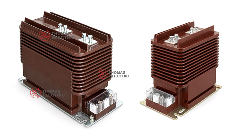
The fully enclosed epoxy resin cast body uses a ribbed external insulation structure for improved creepage path and mechanical stability. A lower secondary terminal box provides organized wiring access for multiple secondary groups. This makes the LZZB9-24/220b/4S suitable for indoor 24kV switchgear, industrial power systems, distribution substations and utility feeder panels.
Product Display


| Item | Specification |
|---|---|
| Product name | Indoor Epoxy Cast-Resin Current Transformer |
| Model | LZZB9-24/220b/4S |
| Application | Instrument transformer for current measurement, metering and protection |
| Operation condition | Indoor |
| Structure | Fully enclosed epoxy resin cast structure with ribbed insulation body |
| Voltage class | 20kV, 22kV and 24kV class medium-voltage systems |
| Rated insulation level | 24/65/125kV |
| Rated secondary current | 5A or 1A |
| Secondary configuration | 4S multi-secondary winding groups |
Product Positioning
The LZZB9-24/220b/4S is best written as a 24kV indoor multi-secondary CT for switchgear metering and protection. Its selling point is not broad waterproof marketing, but engineering-grade insulation coordination, multiple secondary outputs and high-current switchgear compatibility.
| Positioning Point | Technical Meaning | Website Expression |
|---|---|---|
| 24kV platform | Higher insulation level than 12kV CTs | 24/65/125kV insulation for 20kV, 22kV and 24kV switchgear |
| 4S secondary design | Four independent secondary winding groups | Independent outputs for metering, measurement and protection circuits |
| Ribbed resin body | Longer external insulation path | Ribbed epoxy cast-resin body for indoor MV insulation reliability |
| High current range | Supports feeder CT applications up to 3150A | Suitable for high-current indoor switchgear feeders |
| Indoor switchgear use | Designed for cabinet/substation installation | For indoor panels, substations and industrial distribution systems |
Applications
- 20kV, 22kV and 24kV indoor medium-voltage switchgear
- Utility distribution substations and industrial power distribution rooms
- Incoming feeders, outgoing feeders, bus-section panels and metering panels
- Current measurement and electric energy metering circuits
- Relay protection circuits using 5P10 or 5P20 protection classes
- SCADA, feeder monitoring and power-quality monitoring signal circuits
Features
- 24kV insulation class: 24/65/125kV insulation level for 20kV, 22kV and 24kV indoor switchgear.
- 4S multi-secondary design: Four secondary winding groups can be allocated to metering, measurement, protection and backup protection.
- Fully enclosed epoxy casting: Resin-sealed structure improves dielectric strength, moisture resistance and mechanical stability.
- Ribbed insulation body: External ribs increase insulation path and support reliable indoor MV operation.
- Wide current range: Catalogue data covers 20A to 3150A primary current groups for different feeder capacities.
- IEC-oriented documentation: Technical wording can follow IEC 61869-1 and IEC 61869-2 for international projects.
Operating Principle
The LZZB9-24/220b/4S converts the primary current of a 20kV / 22kV / 24kV circuit into standard 5A or 1A secondary current signals. The magnetic cores and secondary windings are cast inside the epoxy resin body. Secondary outputs are connected to meters, relays, energy metering devices and monitoring systems.
For metering windings, the CT must maintain ratio and phase accuracy within the rated burden. For protection windings, it must provide stable output under fault-current conditions. Each 4S secondary group should be assigned to a clear circuit function before production.
Model Designation

Technical Data
| Item | Specification |
|---|---|
| Rated voltage class | 20kV, 22kV and 24kV class indoor systems |
| Rated insulation level | 24/65/125kV |
| Rated frequency | 50Hz or 60Hz |
| Rated secondary current | 5A or 1A |
| Rated primary current | 20A to 3150A reference range according to catalogue data |
| Secondary winding groups | 4S multi-secondary configuration |
| Accuracy class combinations | 0.2(S)/0.2(S)/10P, 0.2(S)/0.5(S)/10P, 0.2(S)/0.5(S)/10P/5(10)P, 0.2(S)/5(10)P/5(10)P |
| Rated output | 15VA, 20VA or 30VA depending on ratio and secondary winding function |
| Short-time thermal current | 150 x I1n, 31.5kA, 45kA, 63kA or 100kA depending on current range |
| Rated dynamic current | 375 x I1n, 80kA, 110kA, 130kA or 160kA depending on current range |
| Ambient temperature | -5°C to +40°C |
| Applicable standards | IEC 61869-1, IEC 61869-2, GB/T 20840.1, GB/T 20840.2; project-specific requirements by agreement |
Selection Table
The following table is reorganized from the catalogue information for website display. Long table headings and accuracy-class cells are split into multiple lines for better responsive layout.
| Rated Primary Current (A) |
Accuracy Class Combination |
Rated Output (VA) |
Rated Short-Time Thermal Current |
Rated Dynamic Current |
|---|---|---|---|---|
| 20-200 | 0.2(S) / 0.2(S) / 10P 0.2(S) / 0.5(S) / 10P 0.2(S) / 0.5(S) / 10P / 5(10)P 0.2(S) / 5(10)P / 5(10)P |
15 / 15 / 20 / 20 | 150 x I1n | 375 x I1n |
| 300 | 15 / 15 / 20 / 20 | 31.5kA | 80kA | |
| 400-500 | 15 / 15 / 20 / 20 | 45kA | 110kA | |
| 600-800 | 15 / 15 / 20 / 20 | 63kA | 130kA | |
| 1000-3150 | 20 / 20 / 30 / 20 | 100kA | 160kA |
Note: This table is for preliminary product-page selection. Final current ratio, accuracy class, rated burden, secondary grouping, short-time thermal current and dynamic current shall be confirmed according to the nameplate, approved drawing and factory test report.
Windings & Terminal Marking
The LZZB9-24/220b/4S is a multi-secondary current transformer. Primary terminals are marked P1 and P2. Secondary terminals are arranged in the terminal box and should be identified according to the ordered 4S configuration and wiring diagram.
| Terminal | Function | Application Note |
|---|---|---|
| P1 / P2 | Primary terminals | Used for primary current direction and polarity reference. |
| 1S1 / 1S2 | First secondary winding | Usually assigned to metering or high-accuracy measurement. |
| 2S1 / 2S2 | Second secondary winding | Usually assigned to measurement or energy metering. |
| 3S1 / 3S2 | Third secondary winding | Usually assigned to relay protection. |
| 4S1 / 4S2 | Fourth secondary winding | Used for backup protection, independent relay circuit or project-specific monitoring. |
| Grounding point | Protective grounding | One point of the secondary circuit should be grounded according to project practice. |
Service Conditions
- Installation site: indoor medium-voltage switchgear
- Rated voltage: 20kV, 22kV and 24kV class systems
- Rated frequency: 50Hz or 60Hz
- Ambient temperature: maximum +40°C, minimum -5°C, daily average not exceeding +30°C
- Atmospheric conditions: no severe pollution, conductive dust, corrosive gas or abnormal condensation
- Altitude, humidity, pollution level and seismic requirements should be confirmed according to project specification.
Standards and Compliance
For international project documentation, the LZZB9-24/220b/4S current transformer should be specified according to IEC 61869-1 and IEC 61869-2. For Chinese standard documentation, GB/T 20840.1 and GB/T 20840.2 can be used. The supplied catalogue also references GB20840.2-2014 and IEC61869-2:2012 as the product standard basis.
Installation and Dimensions

Dimensions
| Dimension Item | Reference Value / Note |
|---|---|
| Overall length | Approx. 475mm reference from catalogue drawing |
| Body length | Approx. 420mm reference |
| Overall height | Approx. 274mm reference |
| Overall width | Approx. 220mm reference |
| Primary terminal arrangement | Top primary terminal layout; terminal hole pattern differs by current range |
| Current range drawing | Separate terminal layouts for 20-1250A and 1500-3000A ranges |
| Secondary terminal box | Lower side terminal box for multi-secondary wiring access |
The CT should be installed inside indoor 24kV switchgear using the approved base mounting holes. Before switchgear production, confirm primary terminal orientation, busbar connection pattern, terminal hole size, secondary terminal direction, grounding position, insulation clearance and maintenance space. For high-current ratings, the primary terminal layout should be checked against the corresponding 1500A-3000A drawing.
Safety Notes
- Confirm voltage class, insulation level, current ratio, secondary current, accuracy class and rated burden before production.
- Verify 4S secondary winding allocation before wiring meters, relays and monitoring devices.
- Check primary terminal spacing, mounting holes, busbar clearance and secondary terminal access before switchgear assembly.
- The CT secondary circuit must not be open-circuited while primary current is flowing.
- Before disconnecting meters or relays, short-circuit the secondary circuit with an approved shorting device.
- One point of the secondary circuit should be reliably grounded according to local electrical safety regulations.
- Installation and commissioning shall be performed by qualified medium-voltage electrical personnel.
Ordering Info
- Product model: LZZB9-24/220b/4S
- Voltage class: 20kV, 22kV or 24kV class
- Rated insulation level: 24/65/125kV
- Rated primary current and transformation ratio
- Rated secondary current: 5A or 1A
- Accuracy class combination for each 4S secondary winding
- Rated burden for each secondary winding
- Rated short-time thermal current and dynamic current
- Primary terminal drawing for the selected current range
- Secondary terminal diagram, terminal marking, routine test report, certificate and label language
Selection Guide
- Confirm voltage platform: Select this model for 20kV / 22kV / 24kV class indoor switchgear, not for 12kV systems.
- Confirm 4S requirement: Use this model when the project needs multiple independent secondary outputs.
- Select current ratio: Choose the primary current according to feeder load and switchgear rating.
- Assign each secondary: Allocate 1S, 2S, 3S and 4S to metering, measurement, protection and backup protection.
- Confirm burden: Check the total meter, relay, terminal and cable burden for every secondary group.
- Check withstand rating: Verify Ith and Idyn against switchgear fault level.
- Approve drawings: Confirm terminal layout, mounting dimensions and secondary terminal box before production.