Product Overview
The LZZBJ9-10(225b) current transformer is an indoor epoxy cast-resin, fully enclosed support-type current transformer developed for high-current medium-voltage switchgear applications. It is designed for current measurement, energy metering, feeder monitoring and relay protection in 10kV, 11kV and 12kV class indoor AC power distribution systems.
Unlike the previous 150b, 175b and 185b platform pages, this model should be positioned as a large-body, high-current CT structure. The 225b body width is intended for applications where higher primary current, larger busbar interface, stronger mechanical support and more spacious phase clearance are required. It is especially suitable for main incoming panels, high-current feeder panels and switchgear projects where the CT is selected mainly for high primary current capacity rather than compact cabinet size.
The sample data shows a rated primary current range of 3000A to 5000A, with rated output of 30VA, rated short-time thermal current of 63kA and rated dynamic current of 160kA. The primary and secondary windings, together with the annular magnetic core, are encapsulated in the epoxy resin casting body to provide dry-type insulation, mechanical strength and resistance to indoor humidity and pollution.
Product Type
| Item | Specification |
|---|---|
| Product name | Indoor Epoxy Cast-Resin High-Current Current Transformer |
| Model series | LZZBJ9-10(225b) |
| Structure | Indoor, fully enclosed, support-type, epoxy cast-resin insulated structure |
| Voltage class | 10kV, 11kV and 12kV class medium-voltage systems |
| Rated insulation level | 12/42/75kV |
| Rated frequency | 50Hz |
| Rated primary current | 3000A to 5000A reference range |
| Rated output | 30VA reference |
| Installation | Indoor high-current switchgear / busbar support installation |
| Applications | High-current feeder measurement, energy metering, relay protection and main switchgear monitoring |
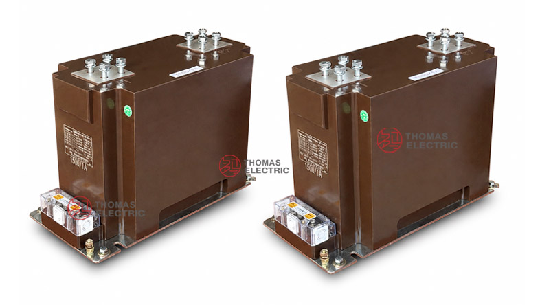
Product Display
 Indoor Epoxy Cast-Resin High-Voltage Current Transformer Thomas Electric")
 Indoor Epoxy Cast-Resin High-Voltage Current Transformer Thomas Electric")
Applications
- Main incoming switchgear for 10kV, 11kV and 12kV class networks
- High-current outgoing feeder panels rated around 3000A to 5000A
- Medium-voltage busbar measurement and protection circuits
- Industrial substations with large transformer feeders or high-load distribution lines
- Utility and plant switchgear requiring 63kA short-time thermal withstand reference
- Projects where primary terminal layout and busbar connection strength are more important than compact CT width
Features
- 225b high-current body: The larger 225b structure provides the mechanical space needed for high-current primary terminal layouts and busbar connection.
- 3000A–5000A selection range: The product is suitable for high-current indoor switchgear where common compact CT structures may not provide sufficient terminal capacity.
- Epoxy cast-resin insulation: The fully enclosed resin body integrates insulation, support and environmental protection into a dry-type CT structure.
- High short-circuit withstand reference: The sample table indicates 63kA rated short-time thermal current and 160kA rated dynamic current for high-current switchgear coordination.
- Measurement and protection combinations: Typical class combinations include 0.2S/5P, 0.2/5P and 0.5/5P configurations for metering and relay protection.
- Large busbar layout support: Different primary terminal drawings are used for 5A–1200A, 1200A–3000A and 4000A–5000A ranges; the final drawing must match the selected current range.
Principle
The LZZBJ9-10(225b) current transformer converts high primary current into a standardized secondary current signal through electromagnetic induction. The primary current produces magnetic flux in the magnetic core, and the secondary winding outputs a proportional signal to meters, relays or monitoring devices. The epoxy resin body provides insulation between the medium-voltage primary side and the secondary circuits.
For this 225b model, engineering selection should focus on high-current coordination. Besides ratio and accuracy, the busbar interface, primary terminal contact area, short-time thermal withstand current, dynamic current and cabinet clearance must be checked together. This is different from compact CT selection, where the main concern is usually installation width.
Model Designation
 Indoor Epoxy Cast-Resin High-Voltage Current Transformer Thomas Electric")
The model code can be interpreted as follows:
| Code | Meaning |
|---|---|
| L | Current transformer |
| Z | Indoor type / support structure |
| Z | Epoxy resin casting insulation |
| B | Protection level available |
| J | Strengthened design |
| 9 | Design serial number |
| 10 | 10kV catalogue voltage class; applicable to 10kV, 11kV and 12kV class systems when insulation coordination is confirmed |
| 225b | Large-width high-current structure dimension code |
Technical Data
| Item | Specification |
|---|---|
| Rated voltage class | 10kV, 11kV and 12kV class indoor systems |
| Rated insulation level | 12/42/75kV |
| Rated frequency | 50Hz |
| Rated primary current | 3000A to 5000A reference range |
| Accuracy combination | 0.2S/5P10/5P20, 0.2/5P10/5P20, 0.5/5P10/5P20, 0.5/5P20/5P20 or project-specific combinations |
| Rated output | 30VA reference according to sample data |
| Rated short-time thermal current | 63kA/1s reference |
| Rated dynamic current | 160kA reference |
| Insulating medium | Epoxy resin |
| Installation type | Indoor support-type / high-current busbar installation |
| Applicable standards | GB 20840.2-2014, IEC 61869-2:2012 and special project requirements |
Terminals
The 225b high-current structure uses large primary terminal arrangements according to the selected current range. Typical primary terminals are marked as P1 / P2. Secondary terminals are arranged in the terminal block according to the specified measuring and protection cores. Because the product is intended for high-current service, the primary terminal drawing must be confirmed before switchgear busbar design.
| Terminal Area |
Function | Engineering Note |
|---|---|---|
| P1 / P2 | Primary high-current terminals | Terminal spacing, contact surface and busbar hole position must follow the approved drawing. |
| Secondary terminal block | Metering and protection outputs | Terminal markings depend on the specified core quantity and accuracy combination. |
| Grounding point | Safety grounding | Grounding shall follow switchgear design and local electrical safety requirements. |
| Shorting device | Secondary maintenance safety | Use shorting terminals before disconnecting meters or relays from energized CT circuits. |
Selection Table
The following table is based on the high-current selection range shown in the sample data. Long accuracy combinations are wrapped into multiple lines to avoid wide table overflow on website layouts.
| Rated
Primary Current (A) |
Accuracy
Class Combination |
Rated
Output (VA) |
Short-Time
Thermal Current |
Rated
Dynamic Current (kA) |
|---|---|---|---|---|
| 3000–5000 | 0.2S / 5P10 / 5P20 0.2 / 5P10 / 5P20 0.5 / 5P10 / 5P20 0.5 / 5P20 / 5P20 0.2 / 0.5 / 5P10 / 5P20 0.2 / 0.5 / 5P20 / 5P20 0.5 / 5P20 / 5P20 / 5P20 |
30 | 63kA | 160 |
Note: If project requirements exceed the listed data, final parameters shall be confirmed by agreement between manufacturer and purchaser. Nameplate data, approved drawings and factory test reports shall prevail.
Busbar Layout
| Current Range | Primary Layout Reference |
Design Focus |
|---|---|---|
| I1n: 5A–1200A | Small-current terminal layout reference | Used only when comparing installation drawings across the product family. |
| I1n: 1200A–3000A | Medium high-current terminal layout | Requires busbar spacing and mounting-hole confirmation. |
| I1n: 4000A–5000A | Large high-current terminal layout | Main reference for this 225b model; confirm busbar width, bolt spacing and cabinet clearance. |
Service Conditions
- Installation location: indoor medium-voltage switchgear
- System voltage: 10kV, 11kV and 12kV class networks
- Rated frequency: 50Hz
- The installation environment should be free from severe vibration, conductive dust, corrosive gas, explosive medium, heavy pollution and abnormal condensation.
- For high-current applications, temperature rise, busbar connection and ventilation conditions shall be reviewed together with the switchgear design.
- For high altitude, coastal or special service environments, insulation coordination and creepage distance shall be confirmed before ordering.
Standards and Compliance
The LZZBJ9-10(225b) current transformer can be supplied according to GB 20840.2-2014, IEC 61869-2:2012 and special project requirements. For international projects, it should be presented as an indoor epoxy cast-resin CT for 10kV, 11kV and 12kV class switchgear. Routine test items generally include ratio test, polarity verification, accuracy test, dielectric withstand test, insulation inspection and appearance inspection.
Installation and Dimensions
 Indoor Epoxy Cast-Resin High-Voltage Current Transformer Thomas Electric")
The 225b model uses a large support-type body and requires careful coordination with the switchgear busbar layout. The supplied drawing shows different primary layouts for 5A–1200A, 1200A–3000A and 4000A–5000A current ranges. For this high-current model, the 4000A–5000A layout is especially important and must be checked before copper busbar processing.
Dimensions
| Item | Dimension / Note |
|---|---|
| Structure code | 225b high-current support-type design |
| Overall body reference | Large-width structure for high-current busbar connection |
| Primary terminal arrangement | Different layouts for 5A–1200A, 1200A–3000A and 4000A–5000A |
| Approximate weight | About 69kg according to supplied drawing |
| Mounting holes | Confirmed according to approved outline drawing |
| Drawing confirmation | Required before switchgear production, replacement or busbar fabrication |
Safety Notes
- Confirm the complete model name LZZBJ9-10(225b) before ordering or installation.
- Check primary busbar size, bolt spacing, contact surface and phase clearance before switchgear production.
- Use the correct outline drawing for the selected current range, especially for 4000A–5000A applications.
- Confirm all secondary terminal markings before connecting meters, relays or monitoring devices.
- The secondary circuit of a current transformer must not be open-circuited when the primary circuit is energized.
- Before disconnecting instruments or relays, short-circuit the corresponding secondary circuit through a proper shorting block.
- Installation and maintenance shall be performed by qualified medium-voltage electrical personnel.
Ordering Info
- Product model: LZZBJ9-10(225b)
- Rated primary current, especially 3000A–5000A high-current requirement
- Rated secondary current and secondary core quantity
- Accuracy class combination and rated output for each secondary circuit
- Rated insulation level and applicable IEC / GB standard
- Required short-time thermal current and rated dynamic current
- Primary terminal drawing, busbar hole size and mounting dimension requirement
- Switchgear layout, cabinet clearance and primary terminal direction
- Quantity, certificates, routine test reports, labeling and packaging requirements
Selection Guide
- Confirm high-current demand: Use this 225b structure when the project requires 3000A–5000A primary current range.
- Check busbar interface: Confirm primary terminal spacing, bolt holes, busbar thickness and connection surface before cabinet design.
- Select accuracy combination: Specify metering and protection classes separately, including 0.2S, 0.2, 0.5 and 5P combinations.
- Verify fault withstand: Confirm 63kA short-time thermal current and 160kA dynamic current compatibility with the switchgear fault level.
- Review temperature rise: High-current CTs require special attention to contact resistance, busbar heating and cabinet ventilation.
- Confirm secondary circuits: Define each secondary core by function, burden, output and terminal marking.
- Approve drawings: Confirm outline drawing, busbar layout, mounting holes and nameplate data before production.