Product Overview
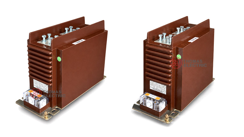
The LZZBJ9-35 current transformer is a dry-type epoxy-resin insulated instrument transformer designed for medium-voltage switchgear applications requiring compact installation, accurate metering and dependable relay protection. With a 195 mm equipment width, this CT is suitable for 800 mm and wider switchgear cabinets, helping panel builders reserve adequate busbar clearance, secondary wiring space and maintenance access while keeping the overall cabinet layout compact.
The product uses high-quality epoxy resin insulation, precision magnetic cores and full copper secondary windings to support stable operation under demanding electrical conditions. It can be specified for IEC 61869 and IEEE C57-based projects, with optional special protection classes such as PR, PX, PXR, TPX, TPY, TPZ or IEEE C-class protection performance according to the project requirement.


Product Type
| Item | Specification |
|---|---|
| Product name | Medium-Voltage Epoxy Resin Current Transformer |
| Model | LZZBJ9-24 |
| Application | Current measurement, energy metering and relay protection |
| Installation condition | Indoor switchgear installation |
| Recommended cabinet width | 800 mm and above |
| Equipment width | 195 mm |
| Insulation medium | High-quality epoxy resin |
| Internal winding material | Full copper winding |
| Rated primary current | 5–600/5 reference range; project-specific ratios available |
| Accuracy class | 0.5 / 0.2 / 0.2S optional; special classes by agreement |

Positioning
This product should be positioned as a compact-width MV current transformer for 800 mm switchgear cabinets. Unlike general-purpose CT descriptions that only focus on accuracy or insulation, this page should clearly tell engineers the installation value: the 195 mm equipment width helps match common medium-voltage cabinet designs while leaving space for busbar connection, phase clearance and secondary terminal access.
| Positioning Point | Technical Meaning | Website Expression |
|---|---|---|
| 195 mm width | Compact CT body width | Designed for 800 mm and wider switchgear cabinets |
| Epoxy insulation | Dry-type, oil-free insulation structure | High-quality epoxy resin insulation with low partial discharge |
| Full copper winding | Stable conductivity and thermal performance | Full copper secondary winding for reliable metering and protection output |
| International standards | Supports IEC and IEEE project documentation | IEC 61869, ANSI/IEEE C57.13 and NEMA-oriented specification support |
| Special protection classes | Advanced relay protection requirements | PR, PX, PXR, TPX, TPY, TPZ or IEEE C100–C800 available by design |
Applications
- Medium-voltage indoor switchgear and distribution panels
- 800 mm and wider cabinet structures requiring compact CT installation
- Energy metering, current measurement and feeder monitoring circuits
- Relay protection and backup protection circuits
- Industrial power distribution, utility substations and grid-side equipment
- Projects requiring IEC 61869 or ANSI/IEEE C57.13 compliance
- High-altitude installations requiring IEC 61869 and IEEE C57 correction up to approximately 5000 m
Features
- Optimized cabinet fit: 195 mm equipment width, suitable for 800 mm and wider medium-voltage cabinets.
- High-quality epoxy resin insulation: Dry-type insulation structure with strong mechanical strength and low partial discharge performance.
- Full copper winding: Good conductivity and current-carrying performance for stable CT operation.
- High metering accuracy: 0.5 / 0.2 / 0.2S classes can be selected according to metering requirements.
- Protection class flexibility: Special classes such as PR, PX, PXR, TPX, TPY, TPZ or IEEE C100–C800 can be engineered by project requirement.
- International project support: IEC 61869, ANSI/IEEE C57.13, NEMA and related certification requirements can be considered at quotation and design stage.
Standards and Certification Capability
The following standards and certification systems can be used as project reference requirements. Final compliance scope depends on the ordered specification, routine test plan, type test requirement and certification documents agreed with the customer.
| Category | Reference Standards / Certifications |
|---|---|
| Instrument transformer standards | IEC 61869, ANSI/IEEE C57.13, NEMA |
| Quality and certification references | ISO 9001, KEMA, CESI, CE, TUV, UL, ASTA |
| Seismic design references | ETGI-1.020, IEEE Standard 693, NCh2369 |
| Structural design references | ASTM A325, ANSI/AISC 360, AWS D1.1 |
| High-altitude correction | According to IEC 61869 and IEEE C57, correction can be considered for installations up to approximately 5000 m |
Technical Data
| Item | Specification |
|---|---|
| Type | Current transformer for current measurement and protection |
| Construction | Dry-type epoxy resin cast structure |
| Application | Industrial and utility power systems, grid service, metering, protection and substations |
| Phase | Single-phase |
| Installation type | Indoor switchgear installation |
| Recommended cabinet width | 800 mm and above |
| Equipment width | 195 mm |
| Primary current range | 5–600/5 reference range; customized current ratios available |
| Secondary current | 5A or 1A according to project requirement |
| Accuracy class | 0.5 / 0.2 / 0.2S optional |
| Special protection classes | PR, PX, PXR, TPX, TPY, TPZ or IEEE C100–C800 by agreement |
| Insulation medium | Epoxy resin |
| Internal material | Full copper winding |
| Primary voltage reference | 24 kV reference platform; final voltage class according to project design |
| Secondary voltage reference | Up to 220 V; minimum 110 V reference where applicable |
Dimensional and Installation Notes
| Item | Recommended Design Note |
|---|---|
| Equipment width | 195 mm |
| Cabinet compatibility | Suitable for 800 mm and wider cabinet structures |
| Installation position | Install according to switchgear primary busbar layout, phase spacing and terminal access direction |
| Busbar clearance | Confirm phase-to-phase and phase-to-ground clearance before cabinet production |
| Secondary wiring | Reserve enough space for terminal cover opening, secondary cable routing and grounding connection |
| Maintenance access | Keep front or side access space for terminal inspection and nameplate reading |
Windings & Terminal Marking
The primary terminals are normally marked P1 and P2. The secondary terminals should be marked according to the number of secondary windings and the approved wiring diagram. For metering and protection configurations, each secondary group should be assigned to a clear function before production.
| Terminal | Function | Application Note |
|---|---|---|
| P1 / P2 | Primary terminals | Used for primary current direction and polarity reference. |
| 1S1 / 1S2 | First secondary winding | Usually assigned to metering or current measurement. |
| 2S1 / 2S2 | Second secondary winding | Usually assigned to relay protection or backup protection. |
| Grounding point | Secondary grounding reference | One point of the secondary circuit should be grounded according to project practice. |
Engineering Selection
- Confirm cabinet size: Use this product where the cabinet width is 800 mm or above and the CT width of 195 mm fits the busbar layout.
- Confirm current ratio: Select the primary current according to feeder load, protection setting and metering range.
- Select accuracy class: Use 0.2S or 0.2 for high-accuracy metering; use 0.5 for general measurement.
- Define protection requirement: Select PR, PX, PXR, TPX, TPY, TPZ or IEEE C-class only when the relay protection study requires it.
- Check altitude: For high-altitude projects up to approximately 5000 m, apply insulation and correction requirements according to IEC 61869 and IEEE C57.
- Check installation clearance: Confirm phase spacing, busbar hole pattern, terminal cover access and secondary wiring path before production.
- Confirm documents: Specify required standard, test report, certification file, label language and packing requirement before order.