Product Overview
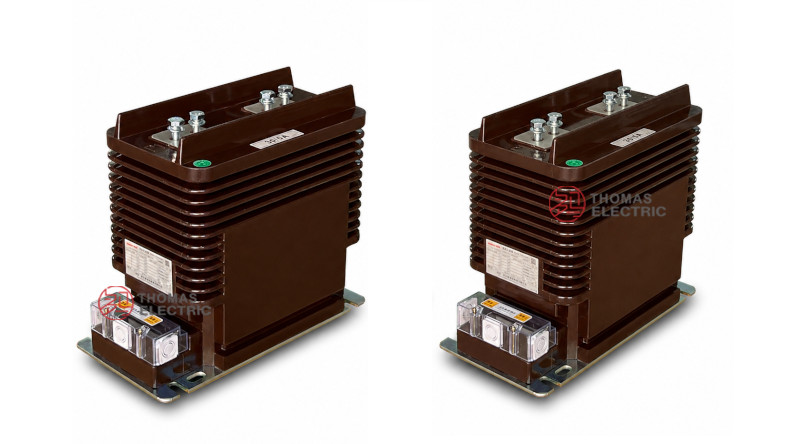
The LZZBJ9-24/180b/2S current transformer is an indoor, single-phase, epoxy resin cast current transformer for 20kV, 22kV and 24kV medium-voltage switchgear. It is designed for current measurement, energy metering, feeder monitoring and relay protection in AC power systems with rated frequency of 50Hz or 60Hz. The product uses a fully enclosed cast-resin body, top busbar-type primary terminals and a lower secondary terminal box for practical switchgear integration.
This model belongs to the same 24kV platform as the 185h and 220b versions, but the 180b/2S should be positioned separately as a compact 24kV dual-secondary CT with charged display device compatibility. When the secondary winding quantity is not more than three cores, a charged display device can be added according to project requirements. This makes the product suitable for compact indoor panels where current measurement, relay protection and live-status indication need to be coordinated in one switchgear bay.


Product Type
| Item | Specification |
|---|---|
| Product name | Indoor Epoxy Cast-Resin Current Transformer |
| Model | LZZBJ9-24/180b/2S |
| Application | Current measurement, energy metering, feeder monitoring and relay protection |
| Operation condition | Indoor |
| Phase | Single-phase |
| Installation type | Busbar type / indoor switchgear installation |
| Insulation medium | Epoxy resin |
| Voltage class | 20kV, 22kV and 24kV class medium-voltage systems |
| Rated insulation level | 24/65/125kV |
| Rated frequency | 50Hz or 60Hz |
| Rated secondary current | 5A or 1A |
| Secondary configuration | 2S dual-secondary winding groups |
| Special option | Charged display device can be added when secondary winding quantity is not more than three cores |
Product Positioning
The LZZBJ9-24/180b/2S should not be written as a generic 24kV CT or as a copy of the 185h/2S and 220b/2S pages. Its strongest positioning is a compact indoor 24kV dual-secondary CT for standard metering/protection panels, with optional live indication integration. It is best used where the switchgear needs two independent secondary outputs but may also require a charged display device without increasing the CT platform complexity.
| Positioning Point | Technical Meaning | Website Expression |
|---|---|---|
| 180b structure | Compact structure code for this 24kV platform | Compact 24kV indoor CT for practical panel integration |
| 2S winding design | Two independent secondary winding groups | Separate metering and protection outputs |
| Charged display option | Live indication device can be added under core-count condition | Metering, protection and live-status indication coordination |
| Busbar type installation | Top P1/P2 primary terminal connection | Designed for indoor busbar-connected switchgear panels |
| 24kV insulation platform | 24/65/125kV insulation level | Suitable for 20kV, 22kV and 24kV IEC-oriented projects |
Applications
- 20kV, 22kV and 24kV indoor medium-voltage switchgear
- Compact feeder panels requiring current measurement and relay protection
- Busbar-connected metering panels and distribution switchboards
- Energy metering and current measurement circuits
- Relay protection circuits using 10P10, 10P15, 5P10 or 5P20 accuracy classes
- Switchgear bays requiring optional charged display device integration
- Utility distribution substations and industrial MV power distribution systems
Features
- Compact 180b platform: Suitable for indoor switchgear where CT body size, busbar spacing and terminal access must be balanced.
- Dual-secondary 2S design: Two secondary winding groups support independent metering and protection circuits.
- Charged display compatibility: A charged display device can be added when the secondary winding quantity is not more than three cores.
- 24kV insulation level: Rated insulation level of 24/65/125kV for 20kV, 22kV and 24kV class systems.
- Fully enclosed epoxy casting: Dry-type resin insulation provides mechanical strength, moisture resistance and stable dielectric performance.
- Flexible accuracy combinations: Supports 0.2/0.2, 0.2/0.5, 0.2/10P10, 0.5/10P10, 0.2/10P15, 0.5/10P15 and related options.
Operating Principle
The LZZBJ9-24/180b/2S operates according to electromagnetic induction. Primary current flows through the busbar-type primary terminal structure between P1 and P2. The magnetic flux generated in the internal core induces proportional current signals in the secondary windings. These outputs are then connected to meters, energy metering devices, protection relays or monitoring equipment.
In a typical 2S configuration, the first secondary winding is assigned to metering or measurement, while the second secondary winding is assigned to relay protection. This separation keeps the secondary circuits clear and supports more reliable commissioning and maintenance.
Model Designation

| Code | Meaning |
|---|---|
| L | Current transformer |
| Z | Indoor type / post-type structure reference |
| ZB | Epoxy cast-resin current transformer series |
| J | Reinforced or structural design reference |
| 9 | Design sequence / product platform |
| 24 | 24kV equipment maximum voltage class |
| 180b | Width and structure code for this compact platform |
| 2S | Two secondary winding groups |
Technical Data
| Item | Specification |
|---|---|
| Rated voltage class | 20kV, 22kV and 24kV class indoor systems |
| Rated insulation level | 24/65/125kV |
| Rated frequency | 50Hz or 60Hz |
| Rated secondary current | 5A or 1A |
| Rated primary current | 20A to 1250A reference range according to supplied catalogue data; extended values by agreement |
| Secondary winding groups | 2S dual-secondary configuration |
| Accuracy class combinations | 0.2/0.2, 0.2/0.5, 0.2/10P10, 0.5/10P10, 0.2/10P15, 0.5/10P15 |
| Rated output | 10/10, 10/15, 15/15, 15/20, 10/20 depending on current ratio and accuracy combination |
| Rated short-time thermal current | 150 × I1n, 31.5kA, 45kA, 63kA or 80kA according to current range |
| Rated dynamic current | 375 × I1n, 80kA, 112.5kA, 130kA or 160kA according to current range |
| Ambient temperature | -5°C to +40°C |
| Applicable standards | GB/T 20840.2-2014, IEC 61869-2:2012; legacy IEC 60044-1 references by project agreement |
Selection Table
The following table is reorganized from the supplied catalogue data and adapted for website display. Long headings and accuracy-class cells are split into multiple lines for better responsive layout.
| Rated Primary Current (A) |
Accuracy Class Combination |
Rated Output (VA) |
Rated Short-Time Thermal Current |
Rated Dynamic Current |
|---|---|---|---|---|
| 20, 30, 40, 50, 75, 100, 150 |
0.2 / 0.2 0.2 / 0.5 0.2 / 10P10 0.5 / 10P10 0.2 / 10P15 0.5 / 10P15 |
10 / 10 10 / 15 |
150 × I1n | 375 × I1n |
| 200 | 10 / 10 10 / 15 |
31.5kA | 80kA | |
| 300, 400, 500 | 10 / 10 10 / 15 |
45kA | 112.5kA | |
| 600, 800 | 15 / 15 15 / 20 |
63kA | 130kA | |
| 1000, 1250, 1500 | 10 / 20 15 / 20 15 / 15 |
80kA | 160kA |
Note: The table is for preliminary selection. Final current ratio, rated burden, accuracy class, secondary terminal arrangement, short-time thermal current and dynamic current shall be confirmed according to the nameplate, approved drawing and factory test report.
Windings & Terminal Marking
The supplied wiring diagram shows primary terminals P1 and P2, with two secondary winding groups marked 1S1 / 1S2 and 2S1 / 2S2. One point of the secondary circuit is grounded according to project wiring practice.

| Terminal Marking | Function | Application Note |
|---|---|---|
| P1 / P2 | Primary terminals | Used for primary current direction and polarity reference. |
| 1S1 / 1S2 | First secondary winding | Usually assigned to metering or current measurement. |
| 2S1 / 2S2 | Second secondary winding | Usually assigned to relay protection. |
| Grounding point | Secondary grounding reference | One point of the secondary circuit should be grounded according to project practice. |
| Charged display interface | Optional live indication output | Can be added when the secondary winding quantity is not more than three cores. |
Service Conditions
- Installation: indoor
- Rated voltage: 20kV, 22kV and 24kV class systems
- Rated frequency: 50Hz or 60Hz
- Ambient temperature: -5°C to +40°C
- Installation environment should be free from severe vibration, conductive dust, corrosive gas, explosive media and abnormal condensation.
- For high altitude, high humidity or heavy-pollution projects, insulation coordination and creepage requirements should be confirmed before ordering.
Standards and Compliance
For new international documentation, the LZZBJ9-24/180b/2S should be specified according to IEC 61869-1 and IEC 61869-2. For GB-based documentation, GB/T 20840.1 and GB/T 20840.2 can be used. The supplied catalogue references GB20840.2-2014 and IEC61869-2:2012 as the product standard basis.
Installation and Dimensions

Dimensions
| Dimension Item | Reference Value / Note |
|---|---|
| Overall length | Approx. 347mm reference from drawing |
| Body length | Approx. 300mm reference |
| Overall height | Approx. 303mm reference |
| Body height | Approx. 266mm reference |
| Overall width | Approx. 180mm reference |
| Top terminal spacing | Approx. 138mm / 162mm reference layout |
| Base mounting length | Approx. 300mm reference |
| Primary terminal arrangement | Busbar-type P1 / P2 top terminal structure |
| Applicable drawing range | I1n ≤ 1250A shown in supplied outline drawing |
The transformer should be installed inside indoor 24kV switchgear using the approved base mounting holes. The busbar-type primary terminals should be matched with the cabinet busbar layout before production. Secondary terminal access, grounding position, charged display wiring space and terminal cover opening space must be reserved during panel design.
Safety Notes
- Confirm voltage class, rated insulation level, current ratio, secondary current, accuracy class and rated burden before production.
- Confirm 2S secondary function allocation before wiring meters and protection relays.
- Check primary terminal spacing, busbar position, mounting holes and terminal box access before switchgear assembly.
- The CT secondary circuit must not be open-circuited while primary current is flowing.
- Before disconnecting meters or relays, short-circuit the secondary circuit with an approved shorting device.
- One point of the secondary circuit should be reliably grounded according to local electrical safety regulations.
- Installation and commissioning shall be performed by qualified medium-voltage electrical personnel.
Selection Guide
- Confirm platform: Select this model for compact 24kV indoor switchgear requiring the 180b structural platform.
- Confirm current ratio: Choose the ratio according to feeder current, metering range and relay protection setting.
- Select secondary output: Choose 5A or 1A according to relay, meter and cable burden.
- Assign 2S functions: Use one secondary group for metering or measurement and the other for protection unless the project diagram specifies otherwise.
- Check charged display requirement: Add the charged display device only when the secondary winding quantity and wiring design meet the requirement.
- Confirm installation: Verify busbar spacing, mounting holes, terminal access and grounding point before production.
- Approve documentation: Confirm IEC / GB standard, routine test, label and certificate requirements before order.