Product Overview
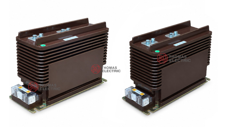
The LZZBJ9-24/180b/4S current transformer is an indoor, single-phase, epoxy resin cast current transformer for 20kV, 22kV and 24kV medium-voltage switchgear. It is designed for current measurement, energy metering, feeder monitoring and relay protection in indoor AC systems with 50Hz or 60Hz rated frequency. Compared with the compact 185h/2S structure, this model is better positioned as a 24kV busbar-type CT with 180b structure and four secondary winding groups, suitable for switchgear projects requiring multiple independent metering, measurement and protection outputs.
The product adopts a fully enclosed epoxy cast-resin body with ribbed external insulation and a busbar-type primary terminal layout. The rated insulation level is 24/65/125kV, and the rated secondary current can be 5A or 1A. The 4S configuration allows up to four secondary circuits, typically used for revenue metering, panel measurement, main protection and backup protection. When the number of secondary windings is no more than three cores, a charged display device can be added according to project requirements.
Product Type


| Item | Specification |
|---|---|
| Product name | Indoor Epoxy Cast-Resin Current Transformer |
| Model | LZZBJ9-24/180b/4S |
| Application | Current measurement, energy metering, feeder monitoring and relay protection |
| Operation condition | Indoor |
| Phase | Single-phase |
| Installation type | Busbar type / indoor switchgear installation |
| Structure | Fully enclosed epoxy resin cast structure with ribbed insulation body |
| Voltage class | 20kV, 22kV and 24kV class medium-voltage systems |
| Rated insulation level | 24/65/125kV |
| Rated frequency | 50Hz or 60Hz |
| Rated secondary current | 5A or 1A |
| Secondary configuration | 4S multi-secondary winding groups |
Product Positioning
The LZZBJ9-24/180b/4S should be written as a multi-output 24kV busbar-type CT for complex switchgear protection and metering schemes. Its value is not only the 24kV insulation platform, but also the ability to provide multiple secondary outputs in one epoxy-cast body. This makes it suitable for switchgear projects where separate signals are required for metering, protection relay, backup protection and monitoring systems.
| Positioning Point | Technical Meaning | Website Expression |
|---|---|---|
| 180b structure | Busbar-type 24kV CT body with wide primary terminal layout | Designed for indoor MV panels requiring busbar-connected CT installation |
| 4S configuration | Four secondary winding groups | Independent metering, measurement, protection and backup protection outputs |
| 24kV platform | Higher insulation class than 12kV CTs | 24/65/125kV insulation for 20kV, 22kV and 24kV systems |
| Charged display option | Can be added when secondary winding quantity is no more than three cores | Supports live indication requirements in selected switchgear designs |
| Ribbed epoxy body | Extended external insulation path | Reliable indoor insulation performance in MV switchgear |
Applications
- 20kV, 22kV and 24kV indoor medium-voltage switchgear
- Incoming feeders, outgoing feeders, bus-section panels and metering panels
- Panels requiring multiple independent secondary outputs
- Energy metering and billing measurement circuits
- Current indication, panel measurement and feeder monitoring circuits
- Main relay protection and backup protection circuits
- Industrial distribution systems, utility substations and grid-side switchgear
Features
- 4S multi-secondary design: Four secondary winding groups support independent metering, measurement, protection and backup protection circuits.
- 24kV insulation platform: Rated insulation level of 24/65/125kV for 20kV, 22kV and 24kV class systems.
- Busbar-type installation: Primary terminals are arranged for direct switchgear busbar connection.
- Fully enclosed epoxy casting: Resin-sealed body provides stable dielectric strength, moisture resistance and mechanical protection.
- Ribbed external insulation: The ribbed body increases external insulation path and supports reliable indoor MV operation.
- Optional charged display integration: When the secondary winding quantity is no more than three cores, a charged display device can be added according to switchgear design.
Operating Principle
The LZZBJ9-24/180b/4S converts primary current in a 20kV / 22kV / 24kV circuit into standardized 5A or 1A secondary current signals. The primary side is connected through the busbar-type P1 / P2 terminals, while the secondary winding groups provide proportional current outputs to meters, relays and monitoring equipment.
Because this model uses a 4S multi-secondary structure, each secondary winding should be assigned to a defined function before production. A typical arrangement may use one secondary group for revenue metering, one for panel measurement, one for main relay protection and one for backup protection or monitoring.
Model Designation

| Code | Meaning |
|---|---|
| L | Current transformer |
| Z | Post type / indoor structure reference |
| Z | Cast epoxy resin insulated structure reference |
| B | Protective / current transformer structure series reference |
| J | Reinforced type |
| 9 | Design sequence |
| 24 | 24kV equipment maximum voltage class |
| 180b | Width and structure code |
| 4S | Four secondary winding groups |
Technical Data
| Item | Specification |
|---|---|
| Rated voltage class | 20kV, 22kV and 24kV class indoor systems |
| Rated insulation level | 24/65/125kV |
| Rated frequency | 50Hz or 60Hz |
| Rated secondary current | 5A or 1A |
| Rated primary current | 20A to 1250A reference range according to supplied catalogue data; high-current layout up to 3000A shown in dimension drawing |
| Secondary winding groups | 4S multi-secondary configuration |
| Accuracy class combinations | 0.2/0.2/0.2, 0.2S/0.5, 0.2/10P/10P10, 0.5/10P10/10P10, 0.2/10P15/10P15, 0.5/10P15/10P15 |
| Rated output | 10/10/10, 10/15/15, 10/10/15, 15/15/20, 15/20/20, 10/20/20VA reference combinations |
| Rated short-time thermal current | 150 × I1n, 31.5kA, 45kA, 63kA or 80kA depending on current range |
| Rated dynamic current | 375 × I1n, 80kA, 112.5kA, 130kA or 160kA depending on current range |
| Ambient temperature | -5°C to +40°C |
| Charged display option | Can be added when the secondary winding is no more than 3 cores |
| Applicable standards | GB/T 20840.1, GB/T 20840.2, IEC 61869-1, IEC 61869-2; legacy IEC 60044-1 references by project agreement |
Selection Table
The following table is reorganized from the catalogue information for website display. Long headers and accuracy-class cells are split into multiple lines to avoid table overflow on product pages.
| Model | Rated Primary Current (A) |
Accuracy Class Combination |
Rated Output (VA) |
Rated Short-Time Thermal Current |
Rated Dynamic Current |
|---|---|---|---|---|---|
| LZZBJ9-24/180b/4S | 20, 30, 40, 50, 75, 100, 150 | 0.2 / 0.2 / 0.2 0.2S / 0.5 0.2 / 10P / 10P10 0.5 / 10P10 / 10P10 0.2 / 10P15 / 10P15 0.5 / 10P15 / 10P15 |
10/10/10 10/15/15 10/10/15 |
150 × I1n | 375 × I1n |
| 200 | 0.2 / 0.2 / 0.2 0.2S / 0.5 0.2 / 10P / 10P10 0.5 / 10P10 / 10P10 |
10/10/10 10/15/15 |
31.5kA | 80kA | |
| 300, 400, 500 | 0.2 / 0.2 / 0.2 0.2S / 0.5 0.2 / 10P / 10P10 0.5 / 10P10 / 10P10 |
15/15/20 15/20/20 10/20/20 |
45kA | 112.5kA | |
| 600, 800 | 0.2 / 0.2 / 0.2 0.2S / 0.5 0.2 / 10P / 10P10 0.5 / 10P10 / 10P10 |
15/15/20 15/20/20 10/20/20 |
63kA | 130kA | |
| 1000, 1500, 1250 | 0.2 / 0.2 / 0.2 0.2S / 0.5 0.2 / 10P / 10P10 0.5 / 10P10 / 10P10 |
15/15/20 15/20/20 10/20/20 |
80kA | 160kA |
Note: This table is for preliminary selection. Final current ratio, rated burden, accuracy class, secondary terminal arrangement, short-time thermal current and dynamic current shall be confirmed according to the nameplate, approved drawing and factory test report.
Windings & Terminal Marking
The primary terminals are marked P1 and P2. The secondary terminals are arranged in the terminal box and should be marked according to the ordered 4S secondary configuration. Multi-secondary CTs require clear function assignment before wiring.
| Terminal Marking | Function | Application Note |
|---|---|---|
| P1 / P2 | Primary terminals | Used for primary current direction and polarity reference. |
| 1S1 / 1S2 | First secondary winding | Usually assigned to revenue metering or high-accuracy measurement. |
| 2S1 / 2S2 | Second secondary winding | Usually assigned to panel measurement or monitoring. |
| 3S1 / 3S2 | Third secondary winding | Usually assigned to relay protection. |
| 4S1 / 4S2 | Fourth secondary winding | Usually assigned to backup protection or project-specific monitoring. |
| Grounding point | Secondary grounding reference | One point of the secondary circuit should be grounded according to project practice. |
Service Conditions
- Installation: indoor
- Rated voltage class: 20kV, 22kV and 24kV systems
- Rated frequency: 50Hz or 60Hz
- Ambient temperature: -5°C to +40°C
- Power factor for burden reference: cosφ = 0.8 lagging
- Anti-fouling level: Grade II reference
- Altitude: ≤1000m for standard service conditions; higher altitude by project confirmation
- No severe pollution, conductive dust, corrosive gas, abnormal condensation or strong vibration at the installation site
Standards and Compliance
For international documentation, the LZZBJ9-24/180b/4S should be specified according to IEC 61869-1 and IEC 61869-2. For GB-based documentation, GB/T 20840.1 and GB/T 20840.2 can be used. Legacy references such as IEC 60044-1 and GB1208-2006 may be retained only when required by old tenders or catalogue comparison.
Installation and Dimensions


Dimensions
| Dimension Item | Reference Value / Note |
|---|---|
| Overall length | Approx. 465mm reference from drawing |
| Body length | Approx. 420mm reference |
| Overall height | Approx. 303mm reference |
| Body height | Approx. 274mm reference |
| Overall width | Approx. 180mm reference |
| Top terminal width | Approx. 100mm reference |
| Current range drawing | Separate mounting layouts are shown for 5–800A and 1000–3000A primary current ranges |
| Secondary terminal box | Lower side terminal box for multi-secondary wiring access |
The transformer should be installed inside indoor 24kV switchgear using the approved base mounting holes. The busbar-type primary terminal arrangement should be checked against the cabinet busbar layout before production. For higher current ratings, use the corresponding 1000–3000A terminal layout drawing. Secondary terminal access, grounding position, terminal cover opening space and wiring route must be reserved during panel design.
Safety Notes
- Confirm voltage class, rated insulation level, current ratio, secondary current, accuracy class and rated burden before production.
- Confirm all 4S secondary function assignments before wiring meters, relays and monitoring devices.
- Check primary terminal spacing, busbar position, mounting holes and terminal box access before switchgear assembly.
- The CT secondary circuit must not be open-circuited while primary current is flowing.
- Before disconnecting meters or relays, short-circuit the secondary circuit with an approved shorting device.
- One point of the secondary circuit should be reliably grounded according to local electrical safety regulations.
- Installation and commissioning shall be performed by qualified medium-voltage electrical personnel.
Selection Guide
- Confirm 24kV platform: Use this model for 20kV, 22kV and 24kV indoor switchgear applications.
- Confirm 4S requirement: Select 4S when separate secondary outputs are required for metering, measurement, protection and backup protection.
- Select current ratio: Choose the primary current according to feeder load, metering range and relay protection setting.
- Assign each secondary: Define the function of 1S, 2S, 3S and 4S before production.
- Check rated burden: Confirm total burden from meters, relays, terminals and secondary cables for each winding.
- Confirm charged display: If a charged display device is required, verify that the secondary winding quantity and cabinet scheme allow it.
- Approve drawings: Confirm current range drawing, primary terminal layout, mounting holes and secondary terminal direction before production.