Product Overview
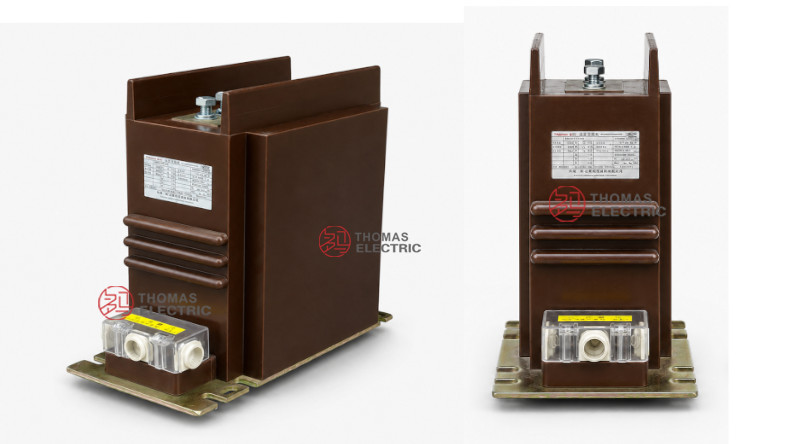
The LZZBJ9-24/185h/2S current transformer is an indoor, single-phase, epoxy resin cast current transformer for 20kV, 22kV and 24kV medium-voltage switchgear. It is designed for current measurement, energy metering and relay protection in indoor AC systems with 50Hz or 60Hz rated frequency. Compared with the larger 220b platform, the 185h structure is better positioned as a compact 24kV busbar-type CT for switchgear projects where installation width, busbar position and terminal access must be carefully controlled.
This product adopts a fully enclosed epoxy cast-resin structure with a multilayer honeycomb-type winding design and cascade magnetic circuit structure. The rated insulation level is 24/65/125kV, and the CT can be supplied with 5A or 1A secondary current. The 2S configuration provides two secondary winding groups, usually arranged for metering / measurement and relay protection. The product is suitable for indoor switchgear applications requiring a compact 24kV CT with clear terminal marking, low partial discharge performance and stable protection output.
Product Type


| Item | Specification |
|---|---|
| Product name | Indoor Epoxy Cast-Resin Current Transformer |
| Model | LZZBJ9-24/185h/2S |
| Application | Current measurement, energy metering and relay protection |
| Operation condition | Indoor |
| Phase | Single-phase |
| Installation type | Busbar type / indoor switchgear installation |
| Winding form | Multilayer honeycomb type |
| Magnetic circuit structure | Cascade type |
| Insulating medium | Epoxy resin |
| Voltage transformation principle | Electromagnetic type |
| Rated insulation level | 24/65/125kV |
| Rated secondary current | 5A or 1A |
Product Positioning
The LZZBJ9-24/185h/2S should not be written as a general 24kV current transformer. Its stronger positioning is a compact 185h structure, dual-secondary, indoor 24kV busbar-type CT. It is especially suitable for switchgear layouts where a smaller CT body, clear P1/P2 busbar terminal arrangement and two independent secondary outputs are preferred.
| Positioning Point | Technical Meaning | Website Expression |
|---|---|---|
| 185h structure | Compact structural width and height platform | Compact 24kV CT for space-sensitive indoor switchgear layouts |
| 2S secondary design | Two secondary winding groups | Separate metering / measurement and protection outputs |
| Busbar type installation | Primary circuit connected through top busbar terminals | Suitable for indoor busbar-connected MV panels |
| Honeycomb winding | Multilayer winding arrangement | Designed for stable accuracy and compact internal structure |
| Cascade magnetic circuit | Magnetic circuit designed for measurement and protection functions | Supports metering and protection class combinations |
Applications
- 20kV, 22kV and 24kV indoor medium-voltage switchgear
- Busbar-connected current measurement and protection panels
- Compact MV feeder cabinets requiring smaller CT installation space
- Energy metering and current measurement circuits
- Relay protection circuits using 5P10, 5P15 or 5P20 classes
- Utility distribution substations and industrial power distribution systems
- SCADA, feeder monitoring and protection relay signal input circuits
Features
- Compact 185h structure: More suitable for constrained indoor switchgear layouts than larger 220b structures.
- 24kV insulation platform: Rated insulation level of 24/65/125kV for 20kV, 22kV and 24kV class systems.
- 2S dual-secondary configuration: Two secondary winding groups support independent metering and protection functions.
- Multilayer honeycomb winding: Helps achieve compact structure, stable output and reliable winding arrangement.
- Cascade magnetic circuit: Supports different metering and protection accuracy class combinations.
- Epoxy cast-resin insulation: Fully enclosed dry-type structure provides strong insulation, moisture resistance and low maintenance requirements.
Operating Principle
The LZZBJ9-24/185h/2S converts high primary current in a 20kV / 22kV / 24kV circuit into standardized 5A or 1A secondary current signals. The primary current flows through the busbar-type primary terminal structure, while the secondary winding outputs proportional current signals to meters, protection relays and monitoring devices.
In the 2S configuration, the two secondary groups should be assigned separately. One group is typically used for metering or measurement, while the other is used for relay protection. This separation improves functional clarity, reduces wiring confusion and supports more reliable protection coordination.
Model Designation

| Code | Meaning |
|---|---|
| L | Current transformer |
| Z | Post type / indoor structure reference |
| Z | Cast epoxy resin insulated structure reference |
| B | Protective / current transformer structure series reference |
| J | Reinforced type |
| 9 | Design sequence |
| 24 | 24kV equipment maximum voltage class |
| 185h | Width and structure code |
| 2S | Two secondary winding groups |
Technical Data
| Item | Specification |
|---|---|
| Rated voltage class | 20kV, 22kV and 24kV class indoor systems |
| Rated insulation level | 24/65/125kV |
| Rated frequency | 50Hz or 60Hz |
| Rated secondary current | 5A or 1A |
| Rated primary current | 20A to 2500A reference range according to supplied catalogue data |
| Secondary winding groups | 2S dual-secondary configuration |
| Accuracy class combinations | 0.2S/0.5, 0.2/0.5, 0.2/5P10, 0.5/5P10, 0.2S/5P20, 0.2/5P20, 0.5S/5P20, 0.5/5P20 and related combinations |
| Rated output | 10VA, 15VA, 20VA or 30VA depending on current ratio and secondary function |
| Rated short-time thermal current | 150 × I1n, 250 × I1n, 300 × I1n, 40kA, 63kA, 80kA or 100kA according to current range |
| Rated dynamic current | 375 × I1n, 625 × I1n, 750 × I1n, 100kA, 160kA, 200kA or 250kA according to current range |
| Ambient temperature | -5°C to +40°C |
| Humidity | Maximum relative humidity at room temperature: 95% |
| Contamination severity | Class II reference |
| Applicable standards | GB/T 20840.1, GB/T 20840.2, IEC 61869-1, IEC 61869-2; legacy IEC 60044-1 references by project agreement |
Selection Table
The following table is reorganized from the supplied catalogue data and adapted for website display. Long headers and accuracy-class cells are split into multiple lines for better responsive layout.
| Rated Primary Current (A) |
Accuracy Class Combination |
Rated Output (VA) |
Rated Short-Time Thermal Current |
Rated Dynamic Current |
|---|---|---|---|---|
| 20–40 | 0.2S / 0.5 0.2 / 0.5 0.2 / 5P10 0.5 / 5P10 |
10 / 15 | 250 × I1n | 625 × I1n |
| 50–100 | 10 / 15 | 300 × I1n | 750 × I1n | |
| 150–250 | 10 / 15 | 40kA | 100kA | |
| 300–2500 | 15 / 20 | 63kA | 160kA | |
| 10–200 | 0.2S / 5P20 0.2 / 5P20 0.5S / 5P20 0.5 / 5P20 0.2S / 0.5 / 5P10 |
10 / 15 / 15 | 150 × I1n | 375 × I1n |
| 300–500 | 10 / 15 / 15 | 40kA | 100kA | |
| 600–1000 | 15 / 20 / 20 | 80kA | 200kA | |
| 1200–2500 | 20 / 20 / 20 / 30 | 100kA | 250kA |
Note: The table is for preliminary selection. Final current ratio, rated burden, accuracy class, secondary terminal arrangement, short-time thermal current and dynamic current shall be confirmed according to the nameplate, approved drawing and factory test report.
Dimensions
| Dimension Item | Reference Value / Note |
|---|---|
| Overall length | Approx. 355mm reference from drawing |
| Body length | Approx. 306mm reference |
| Overall height | Approx. 340mm reference |
| Body height | Approx. 280mm reference |
| Overall width | Approx. 184mm reference |
| Top opening width | Approx. 110mm reference |
| Base mounting length | Approx. 285mm / 275mm reference mounting layout |
| Primary terminal arrangement | Busbar-type P1 / P2 top terminal structure |
Windings & Terminal Marking
The primary outlet terminals are marked P1 and P2. The secondary terminals are marked according to the number of secondary cores and whether tapping is required. The LZZBJ9-24/185h/2S commonly uses two secondary winding groups, but the product platform can support different outlet marking schemes according to project design.
| Terminal Marking | Function | Application Note |
|---|---|---|
| P1 / P2 | Primary terminals | Used for primary current direction and polarity reference. |
| S1 / S2 | One secondary core without tap | Used for single-core measurement or protection configuration. |
| 1S1 / 1S2 | First secondary winding | Usually assigned to metering or current measurement. |
| 2S1 / 2S2 | Second secondary winding | Usually assigned to relay protection. |
| 1S1 / 1S2 / 1S3 | First secondary winding with tap | Used where tapped secondary output is specified. |
| 2S1 / 2S2 / 2S3 | Second secondary winding with tap | Used for two-core tapped configurations where required. |
| Grounding point | Secondary grounding reference | One point of the secondary circuit should be grounded according to project practice. |
Service Conditions
- Installation: indoor
- Ambient temperature: -25°C to +40°C reference range; catalogue also provides -5°C to +40°C general technical data
- Altitude: ≤2000m; higher altitude available on special request
- Humidity: maximum relative humidity at room temperature is 95%
- Contamination severity: class II
- No severe shock or bump at the installation site
- No gas, vapor, chemical deposition, explosive or corrosive media that would seriously affect insulation
Standards and Compliance
For new international documentation, the LZZBJ9-24/185h/2S should be specified according to IEC 61869-1 and IEC 61869-2. For GB-based documentation, GB/T 20840.1 and GB/T 20840.2 can be used. Legacy references such as IEC 60044-1 and GB1208-2006 may be retained only when required by old tenders or catalogue comparison.
Installation and Dimensions

The transformer should be installed inside indoor 24kV switchgear using the approved base mounting holes. The busbar-type primary terminal arrangement should be checked against the cabinet busbar layout before production. Secondary terminal access, grounding position, terminal cover opening space and wiring path must be reserved during panel design.
Safety Notes
- Confirm voltage class, rated insulation level, current ratio, secondary current, accuracy class and rated burden before production.
- Confirm 2S secondary function allocation before wiring meters and protection relays.
- Check primary terminal spacing, busbar position, mounting holes and terminal box access before switchgear assembly.
- The CT secondary circuit must not be open-circuited while primary current is flowing.
- Before disconnecting meters or relays, short-circuit the secondary circuit with an approved shorting device.
- One point of the secondary circuit should be reliably grounded according to local electrical safety regulations.
- Installation and commissioning shall be performed by qualified medium-voltage electrical personnel.
Ordering Info
- Product model: LZZBJ9-24/185h/2S
- Voltage class: 20kV, 22kV or 24kV class
- Rated insulation level: 24/65/125kV
- Rated primary current and transformation ratio
- Rated secondary current: 5A or 1A
- Accuracy class combination for the two secondary windings
- Rated burden for each secondary winding
- Rated short-time thermal current and dynamic current
- Busbar terminal layout and mounting drawing
- Secondary terminal diagram, terminal marking, test report, certificate and label language