Product Overview
The LZZBJ9-24/220b/2S current transformer is an indoor, single-phase, epoxy resin cast current transformer designed for 20kV, 22kV and 24kV class medium-voltage switchgear. It is used for electric energy metering, current measurement, feeder monitoring and relay protection in indoor AC power systems with rated frequency of 50Hz or 60Hz.
This model belongs to the same 24kV platform as the LZZBJ9-24/220b/4S series, but the product positioning should be different. The 2S version is better positioned as a compact dual-secondary 24kV CT for projects that require one metering/measurement secondary and one protection secondary, without the complexity of a four-secondary configuration. It is suitable for standard feeder panels, metering panels and protection panels where a simpler, cleaner secondary wiring scheme is preferred.
The transformer adopts a fully enclosed epoxy cast-resin body with a ribbed external insulation structure. The rated insulation level is 24/65/125kV, making it suitable for IEC-oriented 24kV equipment documentation. The product supports 5A or 1A secondary current, with typical accuracy combinations including 0.2S/0.5, 0.2/0.5, 0.2S/5(10)P10 and 0.5(S)/5(10)P10, depending on project requirements.
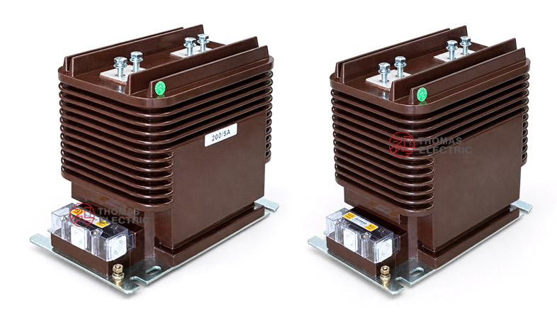
Product Display


Product Type
| Item | Specification |
|---|---|
| Product name | Indoor Epoxy Cast-Resin Current Transformer |
| Model | LZZBJ9-24/220b/2S |
| Application | Instrument transformer for metering, measurement and relay protection |
| Installation condition | Indoor |
| Phase | Single-phase |
| Structure | Fully enclosed epoxy resin cast structure with ribbed insulation body |
| Voltage class | 20kV, 22kV and 24kV class medium-voltage systems |
| Rated insulation level | 24/65/125kV |
| Rated frequency | 50Hz or 60Hz |
| Rated secondary current | 5A or 1A |
| Secondary configuration | 2S dual-secondary winding groups |
Product Positioning
The LZZBJ9-24/220b/2S should be positioned as a 24kV indoor dual-secondary cast-resin CT. It is not an outdoor waterproof CT, and it should not be described with outdoor IP67 or outdoor substation language unless a separate outdoor design is provided. Compared with the 4S version, the 2S version is more focused on standard feeder applications where the engineering requirement is clear: one metering or measurement secondary plus one protection secondary.
| Positioning Point | 2S Product Meaning | Difference from 4S Version |
|---|---|---|
| Secondary design | Two secondary winding groups | Cleaner wiring and simpler circuit allocation than 4S |
| Application focus | Standard metering + protection feeder panels | 4S is more suitable for multi-relay or backup protection systems |
| Engineering selection | Balanced cost, wiring simplicity and functional coverage | Less complex than multi-secondary CTs |
| Voltage platform | 24kV indoor switchgear | Same 24/65/125kV insulation platform as 4S |
| Website positioning | Dual-secondary 24kV indoor CT | Avoid duplicate wording with the 4S page |
Applications
- 20kV, 22kV and 24kV indoor medium-voltage switchgear
- Standard feeder panels requiring one metering core and one protection core
- Utility distribution substations and industrial power distribution systems
- Current measurement and electric energy metering circuits
- Relay protection circuits using 5P10, 10P10 or 5(10)P protection classes
- Medium-voltage panels where simplified secondary wiring is preferred
- SCADA, feeder monitoring and protection relay signal circuits
Features
- Dual-secondary 2S configuration: Provides two independent secondary outputs for metering/measurement and protection functions.
- 24kV insulation platform: Rated insulation level of 24/65/125kV for 20kV, 22kV and 24kV class switchgear.
- Simplified secondary wiring: Compared with 4S designs, the 2S configuration is easier to wire, inspect and maintain.
- Fully enclosed epoxy casting: Resin-sealed body improves dielectric strength, moisture resistance and mechanical stability.
- Ribbed external insulation: The ribbed resin body increases external insulation path and supports reliable indoor MV service.
- Metering and protection accuracy: Supports metering classes such as 0.2S, 0.2, 0.5 and protection classes such as 5P10, 10P10 and 5(10)P20.
Operating Principle
The LZZBJ9-24/220b/2S current transformer converts the primary current of a 20kV / 22kV / 24kV circuit into standardized 5A or 1A secondary current signals. The primary conductor, magnetic core and secondary windings are insulated within the epoxy cast-resin body. The secondary outputs are connected to meters, protection relays and monitoring systems through the terminal box.
For the 2S structure, the first secondary group is normally assigned to metering or measurement, while the second secondary group is assigned to relay protection. This separation improves circuit clarity and helps avoid using one secondary output for incompatible functions.
Model Designation

Technical Data
| Item | Specification |
|---|---|
| Rated voltage class | 20kV, 22kV and 24kV class indoor systems |
| Rated insulation level | 24/65/125kV |
| Rated frequency | 50Hz or 60Hz |
| Rated secondary current | 5A or 1A |
| Rated primary current | 20A to 3150A reference range according to catalogue data |
| Secondary winding groups | 2S dual-secondary configuration |
| Accuracy class combinations | 0.2S/0.5, 0.2/0.5, 0.2S/5(10)P10, 0.5(S)/5(10)P10, 0.2S/5(10)P10, 0.5(S)/5(10)P10 |
| Rated output | 15VA / 15VA, 15VA / 20VA, or 20VA / 30VA depending on current ratio and secondary function |
| Short-time thermal current | 150 × I1n, 31.5kA, 45kA, 63kA or 100kA depending on current range |
| Rated dynamic current | 375 × I1n, 80kA, 110kA, 130kA or 160kA depending on current range |
| Ambient temperature | -5°C to +40°C |
| Applicable standards | IEC 61869-1, IEC 61869-2, GB/T 20840.1, GB/T 20840.2; project-specific requirements by agreement |
Selection Table
The following table is reorganized from the catalogue information for website display. Long table headings and accuracy-class cells are split into multiple lines to improve responsive layout.
| Rated Primary Current (A) |
Accuracy Class Combination |
Rated Output (VA) |
Rated Short-Time Thermal Current |
Rated Dynamic Current |
|---|---|---|---|---|
| 20–200 | 0.2S / 0.5 0.2 / 0.5 0.2(S) / 5(10)P10 0.5(S) / 5(10)P10 |
15 / 15 15 / 20 |
150 × I1n | 375 × I1n |
| 300 | 15 / 15 15 / 20 |
31.5kA | 80kA | |
| 400–500 | 15 / 15 15 / 20 |
45kA | 110kA | |
| 600–800 | 15 / 15 15 / 20 |
63kA | 130kA | |
| 1000–3150 | 15 / 20 20 / 30 |
100kA | 160kA |
Note: This table is for preliminary product-page selection. Final current ratio, accuracy class, rated output, secondary grouping, short-time thermal current and dynamic current shall be confirmed according to the nameplate, approved drawing and factory test report.
Windings & Terminal Marking
The LZZBJ9-24/220b/2S is a dual-secondary current transformer. Primary terminals are marked P1 and P2. Secondary terminals are arranged in the terminal box and should be identified according to the ordered 2S configuration and wiring diagram.
| Terminal | Function | Application Note |
|---|---|---|
| P1 / P2 | Primary terminals | Used for primary current direction and polarity reference. |
| 1S1 / 1S2 | First secondary winding | Usually assigned to metering or measurement. |
| 2S1 / 2S2 | Second secondary winding | Usually assigned to relay protection. |
| Grounding point | Protective grounding | One point of the secondary circuit should be grounded according to project practice. |
Service Conditions
- Installation site: indoor medium-voltage switchgear
- Rated voltage: 20kV, 22kV and 24kV class systems
- Rated frequency: 50Hz or 60Hz
- Ambient temperature: maximum +40°C, minimum -5°C, daily average not exceeding +30°C
- Atmospheric conditions: no severe pollution, conductive dust, corrosive gas or abnormal condensation
- Altitude, humidity, pollution level and seismic requirements should be confirmed according to project specification.
Standards and Compliance
For international project documentation, the LZZBJ9-24/220b/2S current transformer should be specified according to IEC 61869-1 and IEC 61869-2. For Chinese standard documentation, GB/T 20840.1 and GB/T 20840.2 can be used. The supplied catalogue references GB20840.2-2014 and IEC61869-2:2012 as the product standard basis.
Installation and Dimensions

The CT should be installed inside indoor 24kV switchgear using the approved base mounting holes. Before switchgear production, confirm primary terminal orientation, busbar connection pattern, terminal hole size, secondary terminal direction, grounding position, insulation clearance and maintenance space. For high-current ratings, the primary terminal layout should be checked against the corresponding 1500A–3000A drawing.
Dimensions
| Dimension Item | Reference Value / Note |
|---|---|
| Overall length | Approx. 353mm reference from catalogue drawing |
| Body length | Approx. 300mm reference |
| Overall height | Approx. 274mm reference |
| Overall width | Approx. 220mm reference |
| Primary terminal arrangement | Top primary terminal layout; terminal hole pattern differs by current range |
| Current range drawing | Separate terminal layouts for 20–1250A and 1500–3000A ranges |
| Secondary terminal box | Lower side terminal box for 2S secondary wiring access |
Safety Notes
- Confirm voltage class, insulation level, current ratio, secondary current, accuracy class and rated burden before production.
- Verify 2S secondary winding allocation before wiring meters, relays and monitoring devices.
- Check primary terminal spacing, mounting holes, busbar clearance and secondary terminal access before switchgear assembly.
- The CT secondary circuit must not be open-circuited while primary current is flowing.
- Before disconnecting meters or relays, short-circuit the secondary circuit with an approved shorting device.
- One point of the secondary circuit should be reliably grounded according to local electrical safety regulations.
- Installation and commissioning shall be performed by qualified medium-voltage electrical personnel.
Ordering Info
- Product model: LZZBJ9-24/220b/2S
- Voltage class: 20kV, 22kV or 24kV class
- Rated insulation level: 24/65/125kV
- Rated primary current and transformation ratio
- Rated secondary current: 5A or 1A
- Accuracy class combination for the two secondary windings
- Rated burden for each secondary winding
- Rated short-time thermal current and dynamic current
- Primary terminal drawing for the selected current range
- Secondary terminal diagram, terminal marking, routine test report, certificate and label language