Product Overview
The LZZBJ9-36 / LZZBJ9-35/300F indoor epoxy resin cast current transformer is a fully enclosed pillar-type current transformer designed for 35kV / 36kV / 40.5kV medium-voltage power systems. It is used for current measurement, energy metering and relay protection in indoor AC systems with rated frequency of 50Hz or 60Hz. The product adopts epoxy resin casting insulation, with the primary winding, secondary windings and magnetic core sealed inside the resin body to provide stable insulation performance, moisture resistance and mechanical strength for switchgear applications.
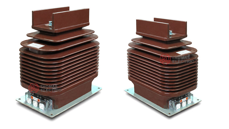
This model should be positioned differently from the previous LZZBJ9-35/270. The LZZBJ9-35/300F structure is a wider 300F-class high-current indoor CT platform, while LZZBJ9-36 is the international voltage-class naming suitable for 36kV equipment systems. The catalogue drawing shows a wide 300mm-class side structure, a compact upper primary terminal arrangement, and two different primary terminal layouts for 10-1000A and 1200-3150A. This makes the product suitable for 35kV / 36kV switchgear feeders requiring large current ratios, multi-core metering/protection windings and high short-circuit withstand capability.
Product Type

| Item | Specification |
|---|---|
| Product name | Indoor Epoxy Resin Cast Current Transformer |
| Models | LZZBJ9-36 / LZZBJ9-35/300F |
| Catalogue reference | LZZBJ9-35/300F/5, AW36/300F/5 reference |
| Installation condition | Indoor |
| Structure | Fully enclosed pillar-type epoxy resin cast structure |
| Structure platform | 300F-class high-current switchgear CT platform |
| Application | Current measurement, energy metering and relay protection |
| System voltage class | 35kV / 36kV / 40.5kV |
| Rated insulation level | 40.5/95/185kV |
| Rated frequency | 50Hz or 60Hz |
| Rated secondary current | 5A or 1A |
| Primary current range | 20A to 3150A reference range according to catalogue data |
| Typical installation | 36kV air-insulated switchgear, high-current feeder cabinet, metering and protection panel |
Model Explanation

- L: Current transformer.
- Z: Pillar-type / support-type structure.
- Z: Epoxy resin casting insulation.
- B: Current transformer series with measurement and protection winding options.
- J: Reinforced / protection-capable design reference.
- 9: Design sequence / product platform code.
- 36: International 36kV equipment class, corresponding to 40.5kV highest system voltage.
- 300F: 300F structural platform, suitable for wider body layout and high-current terminal connection.
Applications
- 35kV, 36kV and 40.5kV indoor medium-voltage AC systems
- 36kV air-insulated switchgear and indoor distribution cabinets
- High-current incoming and outgoing feeder cabinets
- Energy metering, current measurement and power monitoring panels
- Relay protection for transformers, feeders and bus-section circuits
- Industrial substations, utility substations and distribution rooms
- Projects requiring primary current ratings up to 3150A
- Switchgear applications requiring multi-core secondary windings and high short-circuit withstand capability
Features
- 300F-class high-current platform: Designed for larger switchgear layouts and high-current feeder applications.
- International 36kV positioning: LZZBJ9-36 naming is suitable for 36kV equipment documentation, with 40.5/95/185kV insulation level.
- Wide current coverage: Catalogue data covers typical primary current ranges from 20A to 3150A.
- Fully enclosed epoxy resin insulation: The winding and core assembly is sealed inside the resin body for stable insulation and moisture resistance.
- Separate terminal structures: Different primary terminal layouts are used for 10-1000A and 1200-3150A current ranges.
- Multi-core metering and protection: Supports 0.2S / 0.5 measurement cores together with 5P or 10P protection cores.
- High short-circuit withstand: Rated short-time thermal current can reach 100kA and rated dynamic current can reach 250kA in higher current ranges.
- Switchgear-friendly terminal box: The lower terminal section provides clear access for secondary wiring, testing and inspection.
Structure Overview
The LZZBJ9-36 / LZZBJ9-35/300F adopts a fully enclosed epoxy resin cast body with a wide ribbed insulation structure. The upper part forms the primary conductor connection area, while the lower base integrates the secondary terminal section and mounting structure. Compared with smaller indoor CT bodies, the 300F platform provides a wider side structure and stronger cabinet support for higher-current feeder circuits.
The catalogue drawing shows two primary terminal structures. For 10-1000A, a smaller terminal arrangement is used. For 1200-3150A, a wider and stronger terminal arrangement is provided for larger conductors. This structure helps the same CT platform cover both medium-current and high-current switchgear feeders while maintaining the required 40.5kV-class insulation coordination.
Operating Principle
The current transformer converts the primary current in a 35kV / 36kV / 40.5kV circuit into a standardized secondary current, normally 5A or 1A. The secondary output is connected to meters, protection relays, monitoring devices or power management systems. This allows current measurement and protection control to be performed safely while isolating the secondary circuit from the high-voltage primary system.
For metering cores, the CT should maintain ratio error and phase displacement within the selected accuracy class and rated burden. For protection cores, the CT must supply reliable secondary output during fault-current conditions. Current ratio, rated output, accuracy class, short-time thermal current and dynamic current should therefore be selected together according to the system load, relay settings and switchgear fault level.
Technical Data
| Parameter | Specification |
|---|---|
| Models | LZZBJ9-36 / LZZBJ9-35/300F |
| Catalogue reference | LZZBJ9-35/300F/5, AW36/300F/5 reference |
| Product type | Indoor epoxy resin cast current transformer |
| System voltage class | 35kV / 36kV / 40.5kV |
| Rated insulation level | 40.5/95/185kV |
| Rated frequency | 50Hz or 60Hz |
| Rated secondary current | 5A or 1A |
| Primary current range | 20A to 3150A reference range |
| Accuracy combinations | 0.2S/0.5/5P10/5P10, 0.2S/0.5/5P15/5P15, 0.2S/0.5/5P20/5P20, 0.2S/0.5/5P30/5P30, 0.2S/0.5/5P40/5P40 and related combinations |
| Rated output | 30/30/100/100VA, 30/30/80/80VA, 30/30/60/60VA, 30/30/40/40VA, 30/30/30/30VA and project-specific combinations |
| Rated short-time thermal current | 150 x I1n, 200 x I1n, 31.5kA, 45kA, 63kA, 80kA or 100kA according to current range |
| Rated dynamic current | 375 x I1n, 500 x I1n, 100kA, 112.5kA, 160kA, 200kA or 250kA according to current range |
| Ambient temperature | -25°C to +40°C |
| Applicable standards | IEC 61869-1, IEC 61869-2, GB/T 20840.1, GB/T 20840.2; legacy GB20840.1-2010 reference by agreement |
Selection Table
| Rated Primary Current (A) |
Accuracy Class Combination |
Rated Output (VA) |
Rated Short-Time Thermal Current |
Rated Dynamic Current |
|---|---|---|---|---|
| 20-40 | 0.2S / 0.5 / 5P10 / 5P10 0.2S / 0.5 / 5P15 / 5P15 0.2S / 0.5 / 5P20 / 5P20 0.2S / 0.5 / 5P30 / 5P30 0.2S / 0.5 / 5P40 / 5P40 |
30/30/100/100 | 150 x I1n | 375 x I1n |
| 50-100 | 30/30/100/100 | 200 x I1n | 500 x I1n | |
| 150-250 | 30/30/80/80 | 31.5kA | 100kA | |
| 300-400 | 30/30/60/60 | 45kA | 112.5kA | |
| 500-600 | 30/30/40/40 | 63kA | 160kA | |
| 750-800 | 30/30/30/30 | 80kA | 200kA | |
| 1000-3150 | Project-specific output | 100kA | 250kA |
Alternative Output Configuration
| Rated Primary Current (A) |
Accuracy Class Combination |
Rated Output (VA) |
Rated Short-Time Thermal Current |
Rated Dynamic Current |
|---|---|---|---|---|
| 20-40 | 0.2S / 0.5 / 5P10 / 10P10 / 5P10 / 10P10 0.2S / 0.5 / 5P15 / 10P15 / 5P15 / 10P15 0.2S / 0.5 / 5P20 / 10P20 / 5P20 / 10P20 0.2S / 0.5 / 5P30 / 10P30 / 5P30 / 10P30 0.2S / 0.5 / 5P40 / 10P40 / 5P40 / 10P40 |
30/30/80/80/80 | 150 x I1n | 375 x I1n |
| 50-100 | 30/30/80/80/80 | 200 x I1n | 500 x I1n | |
| 150-250 | 30/30/50/50/50 | 31.5kA | 100kA | |
| 300-400 | 30/30/40/40/40 | 45kA | 112.5kA | |
| 500-600 | 30/30/20/20/20 | 63kA | 160kA | |
| 750-800 | 30/30/15/15/15 | 80kA | 200kA | |
| 1000-3150 | Project-specific output | 100kA | 250kA |
Note: If required parameters exceed the above reference range, they can be confirmed by technical agreement between manufacturer and purchaser.
Operating Conditions
- Installation: Indoor installation for 35kV / 36kV / 40.5kV switchgear and distribution systems.
- Rated frequency: 50Hz or 60Hz.
- Ambient temperature: -25°C to +40°C.
- Site condition: No severe vibration, shock or mechanical impact at the installation site.
- Air quality: Ambient air should not be seriously polluted by dust, smoke, corrosive gases, vapours or salt.
- Humidity: Indoor service without severe condensation; special requirements should be confirmed by project agreement.
- Maintenance: Keep the epoxy resin surface clean and dry to maintain insulation performance.
- Installation check: Confirm the correct terminal layout according to the selected primary current range.
Installation and Dimensions

The LZZBJ9-36 / LZZBJ9-35/300F is mounted inside 36kV-class air-insulated switchgear or indoor distribution cabinets. The supplied drawing shows a 300mm-class side width and a high-current terminal structure. Reference dimensions include an overall height of approximately 536mm, a body/base length of approximately 490mm, a side width of approximately 300mm, and an upper terminal width of approximately 190mm. Final dimensions must follow the approved project drawing.
| Installation Item | Recommended Check Point |
|---|---|
| Switchgear space | Confirm overall height, base length, side width and terminal access space. |
| Current range layout | Use the correct terminal structure for 10-1000A or 1200-3150A ranges. |
| Primary terminals | Check P1 / P2 direction, conductor connection method and insulation clearance. |
| Secondary terminal area | Reserve wiring, testing and inspection access for secondary circuits. |
| Mounting base | Confirm fixing hole arrangement, base support and grounding position. |
| Electrical clearance | Confirm phase-to-ground and phase-to-phase clearance for 40.5kV equipment class. |
| Drawing confirmation | Use the approved outline drawing and wiring diagram for final production. |
Windings & Terminal Marking
The primary terminals are identified as P1 and P2. Secondary terminals are arranged according to the number of metering and protection windings. Multi-core configurations may include independent metering, monitoring and relay protection outputs.
| Terminal | Function | Application Note |
|---|---|---|
| P1 / P2 | Primary terminals | Used for primary current direction and polarity reference. |
| 1S1 / 1S2 | First secondary winding | Usually assigned to metering or measurement circuit. |
| 2S1 / 2S2 | Second secondary winding | Usually assigned to relay protection circuit. |
| 3S1 / 3S2 | Additional protection winding | Used when multiple protection outputs are required. |
| 4S1 / 4S2 | Additional measurement or protection winding | Used for multi-core configurations according to project requirements. |
| Grounding point | Secondary circuit grounding reference | One point of the secondary circuit should be grounded according to project practice. |
Standards and Compliance
For international product pages, the LZZBJ9-36 / LZZBJ9-35/300F should be specified according to IEC 61869-1 and IEC 61869-2. GB-based documentation can refer to GB/T 20840.1 and GB/T 20840.2. Legacy catalogue references such as GB20840.1-2010 may be retained for tender compatibility, but modern technical pages should use IEC 61869 and GB/T 20840 series as the preferred standard language.