Product Overview
Functional Definition
The PR series dry-type current transformers are precision electromagnetic instruments designed for accurate current measurement, energy metering, and relay protection applications in low-voltage AC power systems (0.66kV class). These transformers utilize electromagnetic induction principles to provide galvanically isolated secondary current signals proportional to primary current.
Key Ratings Snapshot
| Item | Specification (per order / nameplate) |
|---|---|
| System voltage class | 0.66 kV class (low-voltage distribution and industrial applications) |
| Rated frequency | 50 Hz or 60 Hz (specify at ordering) |
| Rated secondary current | 1 A or 5 A |
| Accuracy classes | Protection cores as specified (e.g., 5P10, 10P10, 5P20, 10P20) |
| Rated burden | Per core/winding as specified (VA) |
| Burden power factor | cosφ = 0.8 (lagging) unless otherwise specified by the project standard |
| AC/BIL insulation level | 4 kV / 10 kV |
| Applicable standards | IEC 61869-1 / IEC 61869-2; IEEE C57.13 (where specified) |
| Insulation material options | Insulation tape or epoxy resin cast (customer selectable) |
| Installation environment | Gas-insulated switchgear (SF6 or air) or power transformer bushings (oil-immersed) |
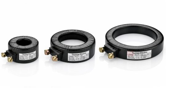
Product Shows

Working Principle
Operating on Faraday’s law of electromagnetic induction, the transformer features a toroidal magnetic core with primary conductor passing through the aperture and secondary windings wound around the core. The magnetic flux generated by primary current induces proportional voltage in the secondary winding, delivering standardized output current (1A or 5A) through connected burden.
System Application Position
- Low-Voltage Distribution: 0.66kV switchgear, motor control centers, and distribution panels
- Energy Metering: Industrial energy measurement and monitoring systems
- Protection Circuits: Overcurrent protection, motor protection, and relay coordination
- SCADA Integration: Supervisory control and data acquisition systems
- Power Quality Monitoring: Load monitoring and power factor correction systems
Structural Form Overview
Bushing-type dry construction with customer-selectable insulation (epoxy resin cast or insulation tape) ensures reliable performance in diverse installation environments. The design accommodates installation in gas-insulated switchgear (GIS) where the CT is placed in SF6 gas or air, or in power transformer bushings where the CT is immersed in insulation oil. Secondary connections are available with either lead wires or secondary terminals to suit installation requirements.
Model Designation
Model Code: PR
- P — Protection-type current transformer
- R — Ring-type / bushing-type construction (toroidal core design)
Configuration Options
The PR series provides flexibility in insulation material selection and secondary termination to match specific application requirements and installation constraints.
Service Conditions
The PR series current transformers are designed for indoor and outdoor operation under normal service conditions in low-voltage power systems.
- Installation environment: Indoor switchgear, outdoor enclosures, or submerged in transformer oil
- Altitude: Not exceeding 1000 m above sea level (higher altitude shall be specified for engineering confirmation)
- Ambient temperature: -25°C to +55°C (air installation); per transformer oil specification (oil-immersed)
- Relative humidity: Daily average ≤ 95%, monthly average ≤ 90% (at +20°C reference)
- Environmental conditions: Free from corrosive gases or vapors; free from explosive or flammable media (except transformer oil); no severe vibration, mechanical shock, or impact
Construction
Construction Design
- Structure: Dry-type bushing (ring-type) for low-voltage switchgear and transformer applications
- Insulation options: Epoxy resin cast (fully enclosed) or insulation tape wrapping
- Core: Ring-type (toroidal) magnetic core design for optimal electromagnetic performance
- Installation media: Air, SF6 gas (GIS applications), or transformer oil immersion
Insulation material selection depends on application environment. Epoxy resin provides superior moisture resistance and mechanical strength for air/SF6 installations. Insulation tape construction is suitable for cost-sensitive applications or oil-immersed installations where the transformer oil provides additional dielectric support.
Windings & Terminal Marking
- Primary terminals: P1 / P2 (through-conductor bushing design)
- Secondary terminals: S1 / S2 (or 1S1 / 1S2 for multi-core configurations)
- Secondary options: Lead wires or screw terminals (specify at ordering)
Terminal markings follow standard CT polarity conventions per IEC 61869-2. Under normal operating conditions, the reference current direction is defined from P1 to P2. Correct terminal identification shall be observed to ensure metering and protection performance.
Technical Data
This section provides selection-oriented technical data for the PR series dry-type bushing current transformer used in 0.66 kV class AC systems (50 Hz or 60 Hz). Data shown below is intended for preliminary selection of accuracy class, rated burden, and protection performance.
Definitions: Accuracy class indicates CT performance for protection applications (5P or 10P classifications). Rated output (VA) is specified per secondary core. Multi-ratio indicates availability of tapped secondary windings for flexible ratio selection.
Notation: Protection class designation (e.g., 5P10) indicates composite error limit at rated accuracy limit primary current (ALF = 10 times rated current). Acceptance shall be based on nameplate values and factory test report.
Performance Parameters
| Parameter | Specification |
|---|---|
| Protection accuracy classes available | 5P10, 10P10 (most common); 5P20, 10P20 (available upon request) |
| Rated secondary current | 1 A or 5 A (specify at ordering) |
| Rated burden range | 2.5 VA to 30 VA (typical); custom burden available |
| Multi-ratio capability | Available with tapped secondary windings (specify ratios at ordering) |
| Insulation level (AC/BIL) | 4 kV / 10 kV |
| Frequency | 50 Hz or 60 Hz (type-tested) |
Custom Sizing & Configuration
CT aperture dimensions, core size, and insulation thickness can be customized to match specific bushing diameters, current ratings, and installation constraints. Engineering support is available for application-specific design including:
- Burden calculation and circuit impedance assessment
- Accuracy verification for specified operating conditions
- Mechanical integration with switchgear or transformer bushings
- Environmental qualification for SF6 or oil-immersed installations
Standards & Normative References
| Standard | Title | Application |
|---|---|---|
| IEC 61869-1 | Instrument Transformers – Part 1: General Requirements | General requirements |
| IEC 61869-2 | Instrument Transformers – Part 2: Additional Requirements for Current Transformers | CT-specific requirements |
| IEEE C57.13 | Standard Requirements for Instrument Transformers | North America project reference (where specified) |
Factory Testing Compliance
- Routine tests per applicable IEC/IEEE requirements (including polarity/marking, ratio verification, and accuracy verification per specified class and burden)
- Dielectric tests per insulation coordination requirements and applicable standard
- Visual and dimensional inspection including marking and workmanship conformity
- Type tests as required by the project specification (including temperature rise, short-time current withstand where specified)
Installation & Dimensions

- Aperture dimensions shall match the primary bushing or conductor diameter with adequate clearance for installation.
- The transformer shall be securely positioned using mechanical supports or mounting brackets as appropriate for the installation type.
- For oil-immersed installations, CT shall be fully submerged in transformer oil with adequate oil circulation for cooling.
- For SF6 installations, gas pressure and purity requirements shall comply with GIS manufacturer specifications.
- Adequate clearance shall be maintained for secondary wiring access and maintenance.
Dimensional Drawings
Custom dimensional drawings are provided with each order showing:
- CT aperture diameter (inner diameter for bushing passage)
- Overall outer diameter and height dimensions
- Secondary terminal arrangement and wire exit points
- Mounting features (where applicable)
Safety Notes
- Secondary circuit must never be left open when the transformer is energized, as dangerous high voltage may appear across the secondary terminals.
- During inspection or maintenance, the secondary circuit shall be short-circuited before disconnecting any instruments.
- One point of the secondary circuit should be reliably grounded in accordance with applicable standards.
- All installation and maintenance work shall comply with local electrical safety regulations.
- For oil-immersed installations, observe transformer oil handling and fire safety requirements.
- For SF6 installations, follow gas handling procedures per manufacturer requirements and local regulations.
Ordering Information
When placing an order, the required configuration shall be specified according to the local grid requirements, applicable standards, and project technical specification. The following parameters shall be clearly stated for technical confirmation and production release:
- Rated primary current / transformation ratio (or range for multi-ratio designs)
- Rated secondary current (1 A or 5 A)
- Accuracy class requirements (e.g., 5P10, 10P10)
- Rated burden (VA) for secondary winding
- Insulation material (epoxy resin cast or insulation tape)
- Installation environment (air, SF6 gas, or oil-immersed)
- Secondary termination type (lead wires or screw terminals)
- CT aperture diameter (for bushing or conductor fit)
- Frequency (50 Hz or 60 Hz)
Selection Guide
- Determine rated primary current (Ip) based on load rating and expected operating range.
- Select protection accuracy requirements (e.g., 5P10 for standard protection; 10P10 for cost-sensitive applications).
- Confirm rated burden (VA) for secondary circuit based on connected relays and wiring losses.
- Specify insulation material and installation environment (air/SF6/oil) to match application conditions.
- Provide dimensional constraints including bushing diameter and available mounting space.
If local utility or project requirements apply (e.g., specific insulation levels, environmental qualifications, documentation language, or required certificates), specify them at the ordering stage. Custom configurations shall be confirmed by technical agreement and final data sheet prior to production.
Technical FAQs
Q1: How to select CT ratio and rated primary current for a 0.66kV dry-type current transformer?
A: Select CT ratio / rated primary current (Ip) from load continuous current rating and required measurement range, then verify against protection relay coordination requirements and switchgear design.
Q2: What are the differences between 5P and 10P protection accuracy classes?
A: 5P class provides composite error ≤ 5% at rated ALF with phase displacement ≤ 60 minutes. 10P class provides composite error ≤ 10% at rated ALF with no phase error specification. 5P is preferred for precision protection; 10P is acceptable for overcurrent protection applications.
Q3: How to determine rated burden (VA) for 1A/5A CT secondary circuits?
A: Rated burden (VA) shall cover total connected load (relay consumption + wiring loss) for 1A or 5A secondary current. Calculate wiring resistance based on wire gauge and length, then add relay burden per manufacturer specification.
Q4: Can PR series CT be used in both air and oil-immersed installations?
A: Yes. Epoxy resin insulation is suitable for air and SF6 installations. Insulation tape construction is suitable for oil-immersed installations. Specify installation environment at ordering for appropriate material selection.
Q5: What are the advantages of multi-ratio CT configurations?
A: Multi-ratio CTs provide flexibility for field adjustment of transformation ratio without replacing the CT. This accommodates load changes or allows single CT design for multiple applications. However, multi-ratio designs have higher cost and larger physical dimensions.
Q6: What are mandatory secondary handling and polarity requirements (P1/P2, S1/S2)?
A: Do not open-circuit CT secondary under energized primary. Short and ground per project practice. Observe terminal marks P1/P2, S1/S2 for correct polarity per IEC 61869-2 conventions.
Q7: Are dimensional drawings and test reports provided with each order?
A: Yes. Each order includes certified dimensional drawings showing aperture diameter, overall dimensions, and terminal arrangement. Factory test reports documenting routine tests and compliance verification are provided with traceability.