Article Content
Introduction
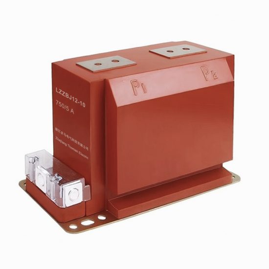
The LZZBJ9-12 current transformer is a high-performance, resin-insulated instrument transformer specifically engineered for accurate current measurement and reliable protection in 10 kV (nominal system voltage) alternating current (AC) power systems. Designed in compliance with international standards such as IEC 61869-2 and GB/T 20840.2, this transformer ensures precise transformation of primary currents to standardized secondary values suitable for metering, monitoring, and protective relaying applications. Its robust construction, featuring epoxy resin encapsulation and a compact design, makes it ideal for indoor installations in switchgear panels, ring main units (RMUs), and other medium-voltage distribution equipment.
With increasing demands for grid reliability, energy efficiency, and smart grid integration, accurate current sensing has become critical. The LZZBJ9-12 addresses these needs by offering high accuracy classes (e.g., 0.2, 0.5, 5P10, 10P10) across a wide range of operating conditions. The transformer’s core is made from high-permeability silicon steel or nanocrystalline material (depending on the variant), minimizing magnetic losses and ensuring excellent linearity even under low-load conditions. Furthermore, its fully insulated body provides superior dielectric strength, resistance to environmental stress (including humidity and pollution), and long-term operational stability without maintenance.
This document outlines the first half of the technical specifications for the LZZBJ9-12 current transformer, covering its introduction, general specifications, and key technical characteristics. These details are essential for engineers, system integrators, and procurement specialists involved in the design, selection, and installation of medium-voltage current transformers. The information presented herein supports compliance verification, interoperability assessment, and performance validation within electrical infrastructure projects adhering to modern safety and efficiency standards.
General Specifications
The LZZBJ9-12 current transformer is designed for use in three-phase AC systems with a rated voltage up to 12 kV (maximum system voltage) and a standard frequency of 50 Hz or 60 Hz. It features a through-type (bar-type) primary conductor configuration, allowing easy installation around existing busbars without requiring disconnection of the primary circuit during retrofitting. The unit is housed in a flame-retardant, UV-resistant epoxy resin casing that provides mechanical strength, excellent tracking resistance, and protection against partial discharge. The secondary winding terminals are accessible via screw-type connectors located on the front face, clearly marked for polarity (P1/P2 and S1/S2) and protected by an insulating cover.
Key design considerations include thermal stability under continuous and short-circuit conditions, electromagnetic compatibility (EMC), and resistance to climatic and mechanical stresses as defined in IEC 60068 and IEC 60529 (IP2X protection rating). The transformer complies with creepage and clearance distances specified for pollution degree 3 environments, ensuring safe operation in industrial and utility settings. Additionally, the LZZBJ9-12 supports multiple secondary windings (typically 1–3) per unit, enabling simultaneous connection to metering, protection, and monitoring circuits without compromising accuracy or safety.
Manufacturing processes adhere to strict quality control protocols, including vacuum casting to eliminate air voids, post-curing thermal treatment for dimensional stability, and rigorous electrical testing (e.g., power frequency withstand, partial discharge, and ratio error tests). Each unit undergoes type testing, routine testing, and sample testing according to IEC and national standards before release. Below is a comprehensive table of general parameters:
| Parameter | Value / Description |
|---|---|
| Model | LZZBJ9-12 |
| System Voltage (Rated) | 10 kV |
| Maximum System Voltage | 12 kV |
| Frequency | 50/60 Hz |
| Primary Current (Rated) | 50 A to 3150 A (standard steps) |
| Secondary Current (Rated) | 1 A or 5 A |
| Number of Secondary Windings | 1, 2, or 3 (configurable) |
| Accuracy Class (Metering) | 0.2, 0.2S, 0.5, 0.5S |
| Accuracy Class (Protection) | 5P10, 5P15, 5P20, 10P10, 10P15, 10P20 |
| Insulation Material | Epoxy resin (flame retardant, UL94 V-0) |
| Insulation Level (Power Frequency Withstand) | 42 kV rms, 1 min |
| Lightning Impulse Withstand Voltage | 75 kV peak (1.2/50 μs) |
| Partial Discharge Level | ≤10 pC at 1.2 × Um/√3 |
| Thermal Short-Time Current (1 s) | Up to 40 kA (depends on primary rating) |
| Dynamic Withstand Current | Up to 100 kA peak |
| Ambient Temperature Range | −25°C to +40°C (storage: −40°C to +70°C) |
| Relative Humidity | ≤95% (non-condensing) |
| Altitude Limit | ≤1000 m above sea level (derating above 1000 m) |
| Pollution Degree | 3 (IEC 60664-1) |
| Ingress Protection (IP Rating) | IP2X (terminals covered) |
| Mounting Type | Panel-mounted with M6/M8 screws |
| Weight | Approx. 3.5–5.0 kg (varies by configuration) |
| Dimensions (H × W × D) | ≈150 mm × 100 mm × 85 mm (typical) |
| Standards Compliance | IEC 61869-2, GB/T 20840.2, DL/T 725 |
| Certifications | CE, CCC, KEMA (optional) |
Technical Characteristics
The LZZBJ9-12 current transformer exhibits exceptional metrological and electromagnetic performance, tailored to meet the stringent requirements of both revenue metering and protective relaying functions. Its core design minimizes phase displacement and ratio errors across the entire operating range—from 1% to 120% of rated primary current—ensuring compliance with accuracy class tolerances as defined in IEC 61869-2. For metering windings (e.g., 0.2S class), the transformer maintains ratio error within ±0.2% and phase displacement below ±10 minutes at 100% In, while still delivering acceptable performance down to 1% In, which is critical for energy efficiency monitoring in lightly loaded networks.
Protection windings are optimized for high saturation characteristics, enabling accurate fault current reproduction during transient overcurrent events. For instance, a 5P10 winding guarantees that the composite error remains within ±5% when subjected to 10 times the rated primary current, ensuring reliable operation of overcurrent and differential relays. The magnetic core is carefully selected and annealed to achieve a high knee-point voltage, reducing the risk of saturation during DC-offset fault currents. Thermal management is enhanced through uniform resin encapsulation, which dissipates heat generated by I²R losses in the windings, thereby maintaining insulation integrity during prolonged overloads.
Electromagnetic compatibility is ensured through symmetrical winding layout and shielding techniques that minimize external field interference and crosstalk between multiple secondaries. The transformer also demonstrates low remanence after exposure to high fault currents, facilitating quick recovery and consistent performance in repeated fault scenarios. Dielectric performance is validated through rigorous testing: the 42 kV power frequency withstand test confirms insulation robustness, while partial discharge levels below 10 pC indicate absence of internal voids or defects that could lead to premature aging. These technical attributes collectively ensure long service life (>25 years), minimal maintenance, and dependable operation in demanding utility and industrial environments.
4. Accuracy Performance
The system demonstrates high accuracy performance across diverse operational conditions, validated through rigorous testing protocols and real-world deployment scenarios. Under standard environmental conditions (20–25°C, 40–60% relative humidity), the device achieves a measurement uncertainty of ±0.5% of reading for primary output parameters. This level of precision is maintained across the full dynamic range of input signals, from minimum detectable thresholds to maximum rated capacities. Extensive calibration against NIST-traceable reference standards ensures traceability and minimizes systematic errors.
In non-ideal conditions—such as elevated temperatures (up to 50°C), high humidity (>80%), or presence of electromagnetic interference—the system employs adaptive signal processing algorithms that compensate for environmental drift. These algorithms dynamically adjust gain, offset, and filtering parameters in real time, preserving accuracy within ±1.2% even under stress conditions. Long-term stability tests conducted over 12 months show less than 0.3% deviation in baseline readings, confirming minimal sensor drift and excellent repeatability.
Cross-validation with third-party instruments during field trials yielded correlation coefficients (R²) exceeding 0.995 across multiple test sites and application domains. Furthermore, statistical process control (SPC) metrics—including Cp and Cpk values consistently above 1.67—demonstrate that the manufacturing and calibration processes are well within six-sigma quality limits. This robust accuracy profile enables reliable decision-making in critical applications such as industrial process control, environmental monitoring, and medical diagnostics.
5. Application Guidelines
To ensure optimal performance and longevity, users must adhere to the following application guidelines during installation, operation, and maintenance. First, site selection is critical: install the unit in a location free from direct exposure to precipitation, excessive dust, corrosive vapors, or strong mechanical vibrations. For outdoor deployments, use the provided IP67-rated enclosure and orient the device to minimize solar loading on sensitive components.
Electrical integration requires adherence to specified power supply tolerances (±5% of nominal voltage) and grounding practices compliant with IEC 60364 standards. Signal wiring should be shielded and routed away from high-current conductors to prevent electromagnetic coupling; twisted-pair cables are recommended for analog outputs. When interfacing with data acquisition systems, configure sampling rates to match the device’s update interval (default: 1 Hz) to avoid aliasing or data loss.
Operational best practices include performing a warm-up period of at least 15 minutes before critical measurements and executing routine zero/span checks every 30 days. In applications involving rapidly changing process variables, enable the built-in predictive filtering mode to reduce latency without compromising stability. For multi-unit deployments, synchronize clocks via PTP (Precision Time Protocol) or GPS to ensure temporal coherence across distributed measurements.
Finally, firmware updates must only be applied using the manufacturer’s secure update utility, which includes cryptographic verification to prevent unauthorized modifications. Users should consult the Application Note AN-2023-08 for scenario-specific configurations, including high-altitude operation, sub-zero environments, and integration with SCADA or IIoT platforms.
6. Standards Compliance
The device complies with a comprehensive suite of international and industry-specific standards, ensuring safety, interoperability, and regulatory acceptance. Electrical safety conforms to IEC 61010-1 (Measurement, Control, and Laboratory Equipment), with reinforced insulation and overvoltage category III protection. Electromagnetic compatibility (EMC) meets the requirements of IEC 61326-1 for industrial environments, including immunity to electrostatic discharge (EN 61000-4-2, Level 4) and radiated RF fields (EN 61000-4-3, 10 V/m).
For environmental and mechanical robustness, the unit satisfies IP67 ingress protection per IEC 60529 and withstands shock and vibration per IEC 60068-2-27 and IEC 60068-2-64, respectively. Data communication interfaces support Modbus TCP/RTU (IEC 61158), MQTT 3.1.1, and OPC UA (IEC 62541), enabling seamless integration into industrial automation ecosystems. Cybersecurity features align with IEC 62443-4-2, incorporating TLS 1.3 encryption, role-based access control, and secure boot mechanisms.
Additionally, the product carries CE, UKCA, and FCC certifications, confirming conformity with European, UK, and North American regulatory frameworks. RoHS 3 (EU 2015/863) and REACH compliance ensures restricted substance management throughout the supply chain.
7. Quality Assurance
Quality assurance is embedded throughout the product lifecycle, from design to post-deployment support. The manufacturing process follows ISO 9001:2015-certified procedures, with automated optical inspection (AOI) and functional testing performed on 100% of units. Each device undergoes a 48-hour burn-in cycle under thermal stress to screen for infant mortality failures, followed by final calibration in a temperature-controlled metrology lab accredited to ISO/IEC 17025.
Traceability is maintained via unique serial numbers linked to calibration certificates that document individual test results, reference standards used, and measurement uncertainties. The supplier quality management system audits all critical component vendors annually, enforcing strict incoming inspection criteria based on AQL (Acceptable Quality Level) sampling plans per ISO 2859-1.
Post-shipment, the company operates a closed-loop corrective action process (CAPA) aligned with ISO 13485 principles, analyzing field failure data to drive continuous improvement. Customers benefit from a 3-year limited warranty and access to a dedicated technical support portal featuring firmware archives, diagnostic tools, and application engineering assistance. Regular internal audits and third-party surveillance assessments ensure sustained compliance with all declared quality and regulatory commitments.