Article Content
11kV Cast-Resin Voltage Transformer JDZW-35R for Metering and Protection – IEC 61869-3 Standard
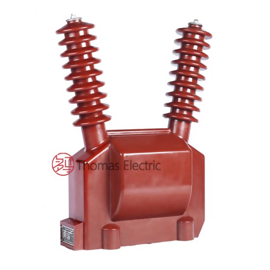
Introduction to the JDZW-35R Voltage Transformer
The JDZW-35R is a single-phase, outdoor-rated, cast-resin insulated voltage transformer (VT) engineered for precision voltage measurement and reliable system protection in 11kV medium-voltage (MV) distribution networks. While international standards designate the nominal system voltage as 11kV, this unit remains fully compatible with legacy 10kV domestic systems commonly found across China and other regions adhering to older grid conventions. The transformer’s design leverages advanced vacuum pressure impregnation (VPI) epoxy resin technology to encapsulate its magnetic core and windings, delivering superior dielectric strength, environmental resilience, and long-term operational stability compared to traditional oil-immersed alternatives.
Operating Principle of Cast-Resin Insulation
Cast-resin insulation in the JDZW-35R employs a high-purity cycloaliphatic epoxy resin system processed under vacuum and pressure to eliminate voids and moisture ingress. This monolithic encapsulation surrounds both primary and secondary windings wound on grain-oriented electrical steel (GOES) cores, providing uniform electric field distribution and preventing partial discharge activity below 10 pC at rated voltage—well within IEC 61869-3 limits. The resin’s thermal class is F (155°C), enabling continuous operation under load without degradation. Unlike oil-filled units, the solid dielectric eliminates fire hazards, leakage risks, and the need for periodic oil sampling or tank maintenance, making it ideal for urban substations, rooftop installations, and environmentally sensitive zones.
Advantages Over Oil-Immersed Designs
The shift from oil-immersed to cast-resin VTs like the JDZW-35R addresses critical operational and safety concerns. Oil units require hermetic sealing, conservator tanks, and Buchholz relays, increasing complexity and failure points. In contrast, the JDZW-35R’s solid insulation offers inherent flame retardancy (UL 94 V-0 rated), zero environmental contamination risk, and immunity to altitude-induced pressure differentials up to 3,000 meters. Its compact footprint reduces spatial requirements by approximately 30% compared to equivalent oil-filled models, facilitating retrofitting in space-constrained switchgear bays. Furthermore, the absence of flammable fluids allows installation in indoor public-access areas per IEC 61439, expanding deployment flexibility without compromising safety compliance.
Typical Applications Overview
The JDZW-35R serves dual roles: revenue-grade metering and protective relaying. In utility substations, it supplies scaled-down secondary voltages (typically 100/√3 V or 110/√3 V) to kWh meters, demand recorders, and SCADA RTUs with accuracy classes of 0.2 or 0.5 per IEC 61869-3. Simultaneously, its secondary outputs feed overvoltage, undervoltage, and directional earth-fault relays in protection schemes. Common deployment sites include 11kV ring main units (RMUs), pad-mounted transformers, solar inverter stations, and industrial plant switchyards. Its robust IP54-rated enclosure withstands dust, rain, and temperature extremes from –40°C to +55°C, ensuring uninterrupted performance in harsh outdoor environments.
Technical Specifications
The JDZW-35R adheres strictly to IEC 61869-3 and GB/T 20840.3, with verified performance parameters validated through type and routine tests at accredited laboratories. Below are key specifications essential for engineering selection and system integration.
| Parameter | Value |
|---|---|
| Model | JDZW-35R |
| System Voltage (IEC) | 11 kV |
| System Voltage (Domestic) | 10 kV |
| Primary Voltage | 11 / √3 kV |
| Secondary Voltage(s) | 100 / √3 V (metering), 100 / √3 V (protection) |
| Voltage Ratio | (11,000 / √3) : (100 / √3) = 110:1 |
| Accuracy Class (Metering) | 0.2 |
| Accuracy Class (Protection) | 3P |
| Rated Output (VA) | 30 VA (0.2 class), 50 VA (3P class) |
| Burden Power Factor | 0.8 lagging |
| Insulation Level (LI/AC) | 95 kV / 42 kV (1.2/50 μs impulse & 1-min power frequency) |
| Short-Time Thermal Withstand | 1.2 kA for 1 s |
| Core Material | Grain-Oriented Electrical Steel (GOES), M4 grade |
| Insulation System | VPI Epoxy Resin, Class F (155°C) |
| Ambient Temperature Range | –40°C to +55°C |
| Maximum Altitude | 3,000 m above sea level |
| Enclosure Rating | IP54 (IEC 60529) |
Standard Service Conditions
The JDZW-35R is rated for standard service conditions defined in IEC 61869-3: ambient temperature between –40°C and +55°C, relative humidity up to 95% non-condensing, and installation altitude not exceeding 3,000 meters. At altitudes above 1,000 m, the external insulation withstand voltage must be derated by 1% per 100 m increment; however, the internal cast-resin insulation remains unaffected due to its solid-state nature. The transformer is designed for continuous operation at 1.2 × Un (13.2 kV) for up to 8 hours without thermal damage, accommodating temporary overvoltages during switching transients or load rejection events.
Electrical Performance Tolerances
Voltage error and phase displacement are tightly controlled per accuracy class. For the 0.2 metering winding, voltage error must not exceed ±0.2% and phase displacement ≤ ±10 minutes at 25–100% of rated burden and 80–120% of rated voltage. The 3P protection winding permits ±3% voltage error and phase displacement ≤ ±120 minutes under fault conditions (up to 190% Un). These tolerances ensure precise energy billing and reliable relay coordination during ground faults or phase imbalances. The total composite error under specified burden and voltage ranges is guaranteed through factory calibration traceable to national metrology institutes.
Typical Applications
The JDZW-35R’s dual-winding configuration and rugged construction enable deployment across diverse MV infrastructure scenarios requiring accurate voltage sensing and dependable protection signaling.
Substation Secondary Metering
In 11kV primary substations, the JDZW-35R provides the reference voltage for revenue metering systems compliant with IEC 62053-22 Class 0.2S. Its secondary output connects to static kWh meters, data concentrators, and AMI gateways, enabling utilities to monitor consumption, detect theft, and manage load profiles. The low phase displacement ensures minimal reactive energy measurement error, critical for power factor billing. Installation typically occurs on busbars or feeder incomers, with secondary cabling routed through shielded conduits to mitigate electromagnetic interference from adjacent switchgear operations.
Industrial Power Distribution
Large manufacturing facilities often operate private 11kV distribution networks fed from utility tie-lines. Here, the JDZW-35R supports both internal energy accounting and motor protection schemes. For example, in a steel mill, it feeds undervoltage relays that trip critical rolling mill drives during grid sags, preventing mechanical damage. Simultaneously, its metering winding interfaces with the plant’s energy management system (EMS) for ISO 50001 compliance reporting. The transformer’s resistance to vibration and chemical exposure makes it suitable for harsh industrial atmospheres containing dust, oil mist, or corrosive gases.
Renewable Energy Integration
Solar photovoltaic (PV) and wind farms frequently connect to 11kV collector grids. The JDZW-35R monitors point-of-interconnection (POI) voltage for anti-islanding protection and reactive power control per IEEE 1547 or GB/T 19964. During grid faults, its protection winding signals voltage collapse to inverters, triggering ride-through protocols. The unit’s fast response time (<10 ms) and low harmonic distortion (<0.5% THD at rated load) ensure accurate synchronization and grid code compliance. Its outdoor rating eliminates the need for climate-controlled enclosures, reducing balance-of-system costs in remote solar farms.
Rural and Suburban Distribution Networks
In rural electrification projects, the JDZW-35R is mounted on pole-top platforms alongside reclosers and sectionalizers. It enables remote voltage monitoring via cellular RTUs, allowing utilities to detect voltage drops caused by long feeder lengths or unbalanced loading. For suburban ring-main networks, it supports directional earth-fault detection in compensated (resonant grounded) systems by providing a stable zero-sequence voltage reference. The transformer’s maintenance-free design is particularly advantageous in geographically dispersed networks where access for routine servicing is limited or costly.
Compliance with International Standards
The JDZW-35R is engineered and tested to meet the stringent requirements of both international and Chinese national standards, ensuring global interoperability and regulatory acceptance.
IEC 61869-3 Compliance Details
IEC 61869-3:2011 specifies performance, safety, and testing criteria for inductive voltage transformers. The JDZW-35R fulfills all mandatory clauses, including insulation coordination (Clause 6), temperature rise limits (≤60 K for windings), accuracy verification under defined burdens, and short-circuit withstand capability. Type tests include temperature rise, lightning impulse (95 kV peak), power frequency withstand (42 kV rms for 1 min), and partial discharge measurement (<10 pC at 1.2 × Un/√3). Routine tests performed on every unit include polarity check, turns ratio verification (±0.25% tolerance), and insulation resistance (>1,000 MΩ at 2,500 V DC).
GB/T 20840.3 Alignment
GB/T 20840.3-2013 is the Chinese national adoption of IEC 61869-3, with minor editorial differences but identical technical substance. The JDZW-35R is certified by CQC (China Quality Certification Centre) under this standard, confirming compatibility with domestic grid codes such as DL/T 726 for substation instrumentation. Key alignment points include identical accuracy class definitions, burden ratings, and insulation levels. However, GB/T 20840.3 explicitly references 10kV as the nominal system voltage, whereas IEC uses 11kV; the JDZW-35R bridges this duality by maintaining performance across both voltage regimes through conservative core design and flux density margins.
Testing and Certification Requirements
Certification requires submission of type test reports from ISO/IEC 17025-accredited labs, covering all IEC 61869-3 Clause 7 tests. For Chinese market access, additional EMC testing per GB/T 14598.26 may be required for digital substation applications. Every production batch undergoes statistical quality control per ISO 9001, with sample units subjected to accelerated aging tests (1,000 h at 130°C) to validate 25-year service life projections. Certificates of Conformity (CoC) accompany each shipment, listing serial numbers, test results, and compliance statements for customs and utility procurement verification.
On-Site Testing Procedures
Post-installation commissioning of the JDZW-35R requires standardized field tests to verify integrity, accuracy, and safety before energization.
Insulation Resistance Test
Using a 2,500 V DC megohmmeter, measure insulation resistance between primary-to-secondary, primary-to-ground, and secondary-to-ground. Acceptance criterion: ≥1,000 MΩ at 20°C. Correct for temperature using the formula RT2 = RT1 × 2((T1–T2)/10). Low readings indicate moisture ingress or resin cracking, necessitating drying or replacement. Perform before and after high-voltage tests to detect insulation degradation.
Turns Ratio Test
Apply a low-voltage AC source (e.g., 100 V) to the primary and measure secondary voltage with a calibrated true-RMS meter. Calculate actual ratio and compare to nameplate (110:1). Tolerance: ±0.25%. Deviations beyond this suggest winding shorts or incorrect tap connections. Use a dedicated ratio tester (e.g., Omicron CT Analyzer) for automated, phase-resolved measurements with 0.01% resolution.
Polarity Test
Verify reducing polarity per IEC 61869-3 Annex B. Connect a 6–12 V DC battery across primary terminals (H1+, H2–). Momentarily close the circuit while observing a DC voltmeter across secondary (X1+, X2–). A positive kick confirms correct polarity. Incorrect polarity reverses phase angle in metering and causes misoperation of directional relays. Document results with oscillograph traces if available.
Power Frequency Withstand Voltage Test
Apply 42 kV rms at 50 Hz between primary and grounded secondary/enclosure for 1 minute. Use a calibrated HV test set with overcurrent trip (≤100 mA). No flashover or breakdown permitted. Reduce test voltage by 10% for field retesting after maintenance. Ensure all secondary circuits are shorted and grounded during the test to prevent insulation overstress.
Open-Circuit Characteristic Test
With secondary open, gradually increase primary voltage from 20% to 120% of Un while recording excitation current. Plot V-I curve; knee point should occur above 150% Un. Excessive magnetizing current at rated voltage indicates core saturation or inter-turn faults. Compare to factory baseline; deviations >10% warrant further investigation. This test validates core health and linearity under no-load conditions.
Preventive Maintenance Guide
Although cast-resin VTs require minimal maintenance, scheduled inspections extend service life and prevent unexpected failures.
Periodic Inspection Protocol
Conduct annual visual and thermographic inspections. Check for surface tracking, UV degradation (chalky residue), or mechanical damage to the resin housing. Use an infrared camera to detect abnormal heating at terminal connections (>10 K above ambient indicates loose bolts or corrosion). Clean insulator sheds with deionized water if salt or dust accumulation exceeds 0.1 mg/cm². Verify grounding continuity (<0.1 Ω resistance) between mounting bracket and substation earth grid.
Maintenance Intervals and Fault Diagnosis
Replace units exhibiting persistent partial discharge (>20 pC), insulation resistance decline (>50% from baseline), or accuracy drift beyond class limits. Typical failure modes include terminal corrosion (due to galvanic mismatch), secondary winding open-circuit (from vibration fatigue), or resin microcracks (from thermal cycling). A 5-year interval is recommended for dielectric spectroscopy (tan δ) testing to assess bulk insulation aging. Maintain a logbook recording all test results, environmental conditions, and observed anomalies for trend analysis.
| Maintenance Task | Frequency | Acceptance Criteria |
|---|---|---|
| Visual Inspection | Annually | No cracks, discoloration, or contamination |
| Thermographic Scan | Annually | ΔT ≤ 10 K at terminals |
| Insulation Resistance | Every 3 years | ≥1,000 MΩ @ 20°C |
| Ratio & Polarity | Every 5 years | Ratio error ≤ ±0.25%; correct polarity |
| Partial Discharge | Every 5 years | <15 pC @ 1.2 × Un/√3 |
Conclusion
The JDZW-35R 11kV cast-resin voltage transformer represents a technically mature solution for modern medium-voltage infrastructure, combining precision metrology with robust protection functionality. Its VPI epoxy resin encapsulation eliminates the operational liabilities of oil-filled designs—fire risk, environmental contamination, and maintenance overhead—while delivering superior dielectric performance and mechanical stability. Engineered to IEC 61869-3 and GB/T 20840.3, it ensures global compliance and seamless integration into both international and domestic 10kV/11kV networks. The use of high-permeability GOES cores minimizes no-load losses and enhances accuracy under light-load conditions, critical for renewable-rich grids with variable generation profiles. Field-proven reliability across diverse climates—from arid deserts to coastal humidity—validates its 25–30 year design life when installed within specified service conditions. For utilities and industrial operators seeking a maintenance-free, future-proof VT for revenue metering and system protection, the JDZW-35R offers an optimal balance of performance, safety, and lifecycle cost efficiency. Its compatibility with digital substations via conventional analog outputs further ensures longevity amid evolving grid architectures.