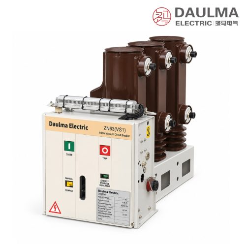
Product Overview
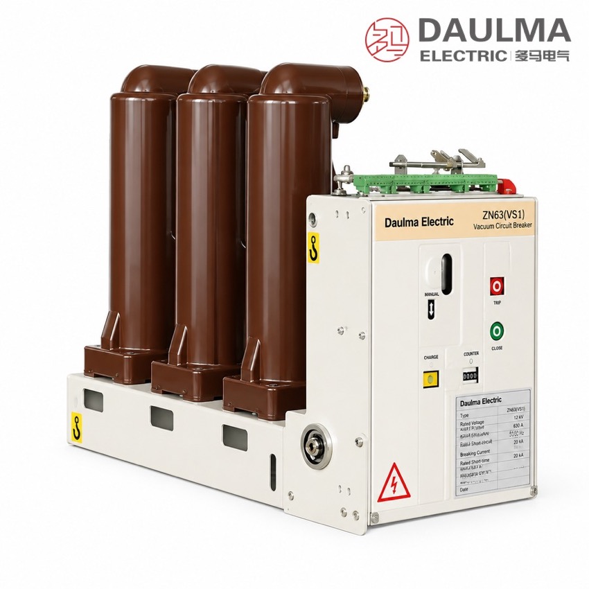
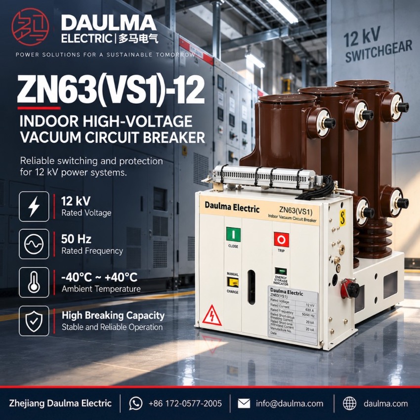
The ZN63(VS1)-12 side-mounted is a three-phase 50 Hz indoor high-voltage vacuum circuit breaker rated 12 kV for control and protection in power networks and in industrial and mining enterprises. Rated currents of 630 A and 1250 A pair with breaking capacities of 20 kA, 25 kA and 31.5 kA, suiting frequent operation at rated current and repeated interruption of short-circuit currents in fixed-pattern metal-enclosed switchgear.
Product Display
Model Designation
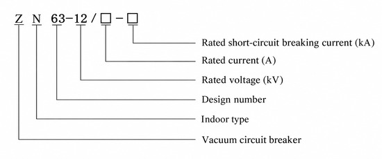
Model format: ZN 63 − 12 / □ − □
- Z — Vacuum circuit breaker
- N — Indoor installation
- 63 — Design sequence number
- 12 — Rated voltage (kV)
- First □ — Rated current (A)
- Second □ — Rated short-circuit breaking current (kA)
Example: ZN63(VS1)-12 / 1250 − 31.5 denotes a 12 kV indoor vacuum circuit breaker with 1250 A rated current and 31.5 kA rated short-circuit breaking current. ZN63 is the GB type code; VS1 is the equivalent common trade name.
Service Conditions
- Ambient temperature: −40 °C to +40 °C
- Altitude: not above 1000 m (higher sites require a correspondingly raised insulation level)
- Seismic intensity: not above degree 8
- Relative humidity: daily average ≤ 95%, monthly average ≤ 90%
- Environment: free from fire, explosion hazard, serious pollution, chemical corrosion and violent vibration
Construction
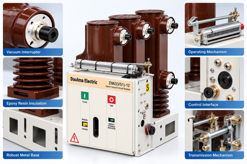
The vacuum interrupter and the operating mechanism are integrated on a common frame. The arc is extinguished in a sealed, maintenance-free vacuum interrupter, giving long electrical life with no fire or explosion risk and no routine overhaul of the interrupting medium.
The mechanism front plate provides close and trip push-buttons, an energy-storage indicator, a manual charging handle and a mechanical operation counter, so breaker position and stored energy are visible at a glance. The compact side-mounted structure is bolted into fixed-pattern metal-enclosed switchgear and supports electric, manual and remote operation with the required interlocking.
Technical Data
| Item | Unit | 20kA | 25kA | 31.5kA |
|---|---|---|---|---|
| Rated Voltage | kV | 12 | ||
| Rated Frequency | Hz | 50 | ||
| Rated Current | A | 630–1250 | 1250 | 1250 |
| Rated Short-Circuit Breaking Current | kA | 20 | 25 | 31.5 |
| Rated Short-Circuit Making Current (Peak) | kA | 50 | 63 | 80 |
| Rated Peak Withstand Current | kA | 50 | 63 | 80 |
| Rated Short-Time Withstand Current (4 s) | kA | 20 | 25 | 31.5 |
| Power Frequency Withstand Voltage 1 min (48 across open contacts) | kV | 42 | ||
| Lightning Impulse Withstand Voltage (85 across open contacts) | kV | 75 | ||
| Rated Operating Sequence | — | O – 0.3 s – CO – 180 s – CO | ||
| Mechanical Life | Operations | 10000 | ||
| Breaking Operations at Rated Short-Circuit Current | Times | 50 | ||
| Closing / Opening Voltage of Mechanism | V | AC/DC 220, 110 | ||
| Contact Gap | mm | 11 ± 1 | ||
Standards
Designed and type-tested to GB/T 1984 and IEC 62271-100 for AC high-voltage circuit breakers, with manufacturing and inspection in accordance with DL/T 402.
Installation & Dimensions
Installation Diagram
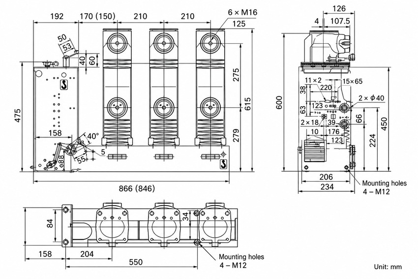
The side-mounted fixed-type breaker is installed inside fixed-pattern metal-enclosed switchgear; each pole is bolted to the panel through its mounting frame. The primary circuit connects to the busbar and cable side through static contacts or cable lugs and the secondary circuit to the control and protection loop through the terminal block; the breaker and frame must be reliably earthed before commissioning.
| Item | Value (mm) |
|---|---|
| Overall Width | 866 (846) |
| Overall Height | 600 |
| Overall Depth | 234 |
| Enclosure (front panel) Height | 475 |
| Pole Spacing | 210 |
| Pole-Center Span (top view) | 550 |
| Base Mounting Holes | 4 × M12 |
| Bushing Mounting Holes | 6 × M16 |