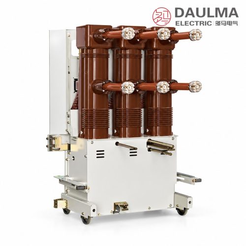
Product Overview
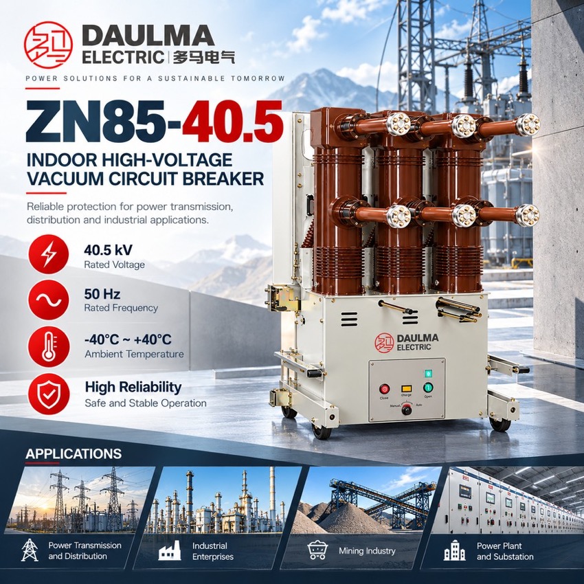
The ZN85-40.5C is a three-phase 50 Hz, 40.5 kV handcart (withdrawable) indoor vacuum circuit breaker for metal-enclosed switchgear in power plants, substations and industrial or mining networks. It makes, carries and breaks load, overload and short-circuit currents, with rated currents of 1250-2000 A, breaking capacity 25 or 31.5 kA and capacitor-bank breaking of 630 A single / 400 A back-to-back.
Product Display
Model Designation
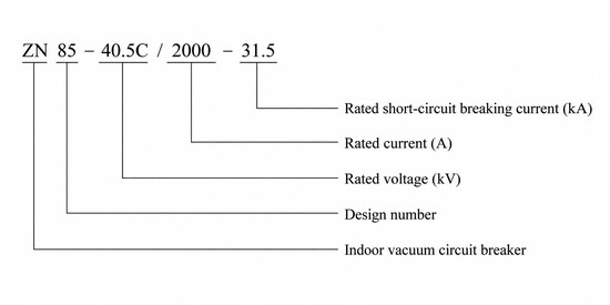
Type code: ZN 85 – 40.5 C / □ – □
- Z — vacuum interrupting medium
- N — indoor service
- 85 — design sequence number
- 40.5 — rated voltage (kV)
- C — handcart (withdrawable) execution
- First □ — rated current (A)
- Second □ — rated short-circuit breaking current (kA)
Example: ZN85-40.5C/2000-31.5 identifies a 40.5 kV withdrawable indoor vacuum circuit breaker of 2000 A rated current and 31.5 kA rated short-circuit breaking current.
Service Conditions
- Ambient temperature: −40 °C to +40 °C
- Altitude: up to 2000 m; sites above this limit require a correspondingly raised rated insulation level
- Relative humidity: daily average ≤ 95%, monthly average ≤ 90%
- Seismic intensity: not exceeding degree 8
- Site free from fire hazard, explosion risk, heavy pollution, chemical corrosion and violent vibration
- Conditions outside these limits: subject to agreement with the manufacturer
Construction
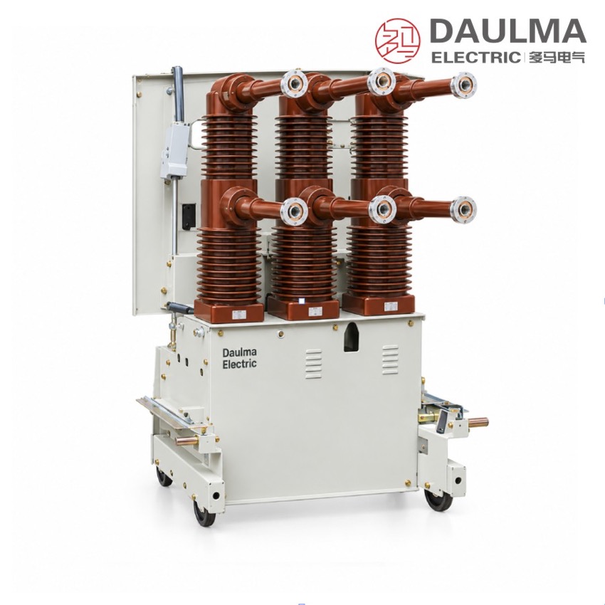
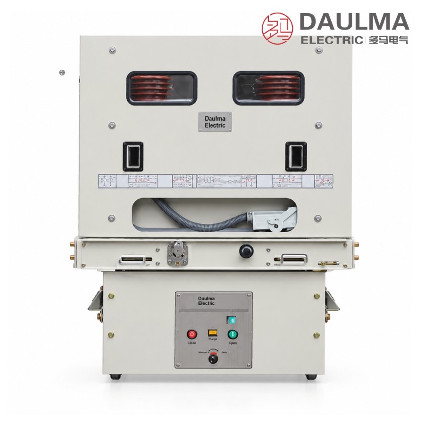
Each phase consists of a sealed vacuum interrupter cast into a solid insulated pole, mounted on a steel handcart frame together with the spring energy-storage operating mechanism. The mechanism stores closing energy in a charged spring, released electrically by the closing coil or manually, while opening is triggered by the opening coil; control and charging circuits accept AC or DC 110 / 220 V.
The complete pole set and mechanism rack in and out of the metal-enclosed switchgear on a chassis that moves between connected, test and disconnected positions, giving visible isolation without de-energising the cubicle. Mechanical interlocks coordinate racking, closing and earthing functions, and the frame carries an earthing terminal bonded to the switchgear body.
Technical Data
| No. | Item | Unit | Data |
|---|---|---|---|
| 1 | Rated voltage | kV | 40.5 |
| 2 | Rated frequency | Hz | 50 |
| 3 | Rated current | A | 1250 1600 2000 |
| 4 | Rated short-circuit breaking current | kA | 25 31.5 |
| 5 | Rated short-time withstand current | kA | 25 31.5 |
| 6 | Rated short-circuit duration | s | 4 |
| 7 | Rated peak withstand current | kA | 63 80 |
| 8 | Rated short-circuit making current (peak) | kA | 63 80 |
| 9 | Rated lightning impulse withstand voltage (peak) | kV | 185 |
| 10 | 1 min power-frequency withstand voltage (RMS) | kV | 95 |
| 11 | Rated short-circuit breaking time | ms | < 80 |
| 12 | Rated operating sequence | — | O – 0.3 s – CO – 180 s – CO |
| 13 | Breaking operations at rated short-circuit current | times | 20 |
| 14 | Rated single capacitor bank breaking current | A | 630 |
| 15 | Back-to-back capacitor bank breaking current | A | 400 |
| 16 | Mechanical life | operations | 10000 |
| 17 | Rated operating voltage (AC/DC) | V | 110 220 |
Standards
The breaker is designed and type-tested to GB/T 1984 and IEC 62271-100 for AC high-voltage circuit breakers, with manufacture and inspection performed in accordance with DL/T 403 for indoor high-voltage vacuum circuit breakers of 3.6 kV to 40.5 kV.
Installation & Dimensions
Installation Diagram
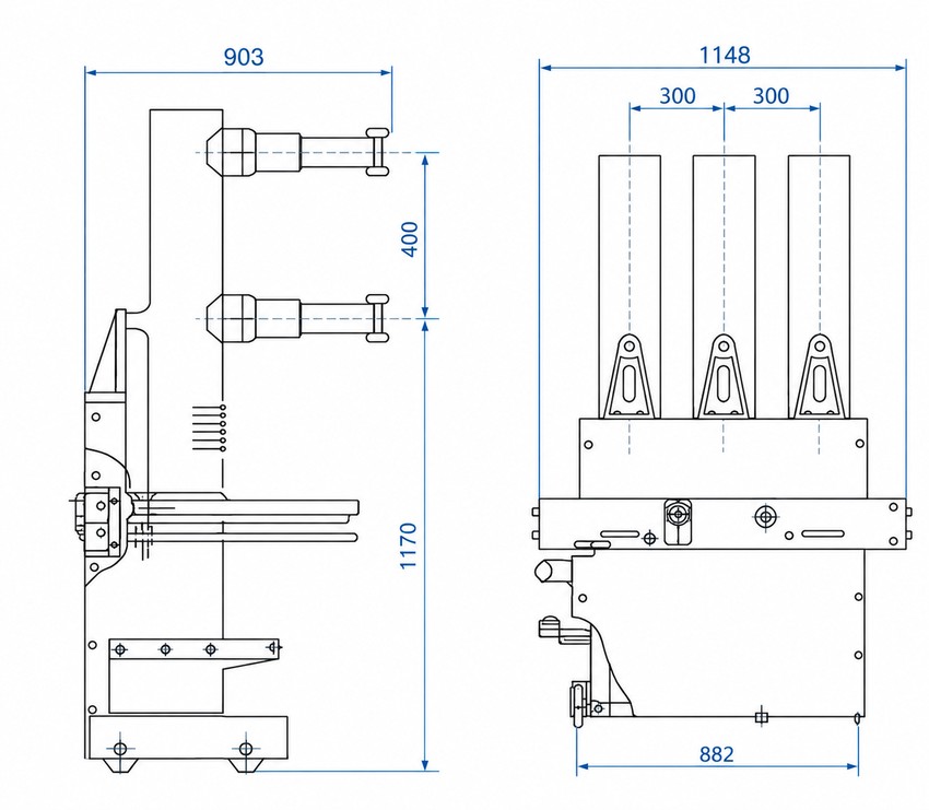
The unit is delivered mounted on its chassis and racked into the metal-enclosed switchgear between connected, test and disconnected positions. Primary current passes through the chassis static contacts to the busbar, secondary circuits route via the terminal block to control, protection and metering loops, and both breaker frame and switchgear body must be earthed before commissioning with all interlocks verified.
| Outline dimension | View | Value (mm) |
|---|---|---|
| Overall width | Front | 1148 |
| Pole (phase) spacing | Front | 300 + 300 |
| Base / wheelbase width | Front | 882 |
| Overall depth | Side | 903 |
| Upper section height | Side | 400 |
| Lower section height | Side | 1170 |