Product Overview
Functional Definition
The AG12-0.72 series current transformers are electromagnetic instruments designed for accurate current measurement and energy metering applications in low-voltage AC power systems. Featuring indoor plastic case construction, these transformers provide galvanically isolated secondary current signals proportional to primary current for use in 0.72kV class distribution networks.
Key Ratings Snapshot
| Item | Specification (per order / nameplate) |
|---|---|
| System voltage class | 0.72 kV class (indoor low-voltage distribution applications) |
| Rated voltage | 720 V |
| Rated frequency | 50 Hz / 60 Hz |
| Rated secondary current | 5 A (standard) |
| Accuracy classes | 1.0, 0.5 per IEC and GB standards |
| Rated burden | 1 VA to 15 VA per core/winding as specified |
| Security factor (FS) | FS < 5 |
| Dielectric test | 4 kVeff, 50 Hz, 1 minute |
| Ambient temperature | −5°C to +55°C |
| Applicable standards | GB1208-2006; IEC60044-1:2003; customer-specific requirements |
| Construction type | Indoor plastic case type |
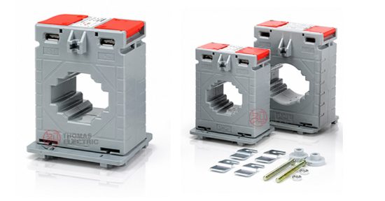
Product Shows


Working Principle
Operating on electromagnetic induction principles, the AG12-0.72 features a magnetic core with primary conductor passing through the aperture and secondary windings wound around the core. The magnetic flux generated by primary current induces proportional voltage in the secondary winding, delivering standardized output current through connected burden. The plastic case provides mechanical protection and electrical insulation suitable for indoor low-voltage applications.
System Application Position
- Low-Voltage Distribution: 0.4-0.72kV switchgear and distribution panels
- Energy Metering: Electricity measurement systems in commercial and industrial facilities
- Load Monitoring: Feeder current monitoring and power quality analysis
- Motor Protection: Overcurrent detection in motor control centers
Structural Form Overview
Plastic case construction provides compact design with integrated mounting features for busbar or conductor installation. The enclosed design ensures protection against dust and mechanical damage while maintaining electrical clearances suitable for low-voltage indoor environments. Multiple aperture sizes accommodate various primary conductor configurations.
Model Designation

Model Code Explanation
AG12-0.72/XX/YY
- AG12 — Product series designation (indoor plastic case current transformer)
- 0.72 — Rated voltage class (kV)
- XX — Rated primary current (A)
- YY — Aperture size designation (mm)
Model Variants
Available model configurations include AG12-0.72/62/30, AG12-0.72/62/40, AG12-0.72/74/40, AG12-0.72/74/50, AG12-0.72/86/60, AG12-0.72/104/80, and AG12-0.72/140/100. Selection depends on primary current rating and conductor size requirements.
Service Conditions
The AG12-0.72 series current transformers are designed for indoor operation under normal service conditions in low-voltage power systems.
- Installation environment: Indoor installation only
- Altitude: Not exceeding 1000 m above sea level (higher altitude requires specification)
- Ambient temperature: −5°C to +55°C
- Relative humidity: Daily average ≤ 95%, monthly average ≤ 90% (at +20°C reference)
- Environmental conditions: Free from corrosive gases or vapors; free from explosive or flammable media; no severe vibration, mechanical shock, or impact
Construction
Construction Design
- Structure: Window-type (busbar pass-through) plastic case design
- Insulation: Plastic housing with integrated insulation system
- Core: Ring-type magnetic core design
- System: Single-core configuration with standardized secondary terminals
The plastic case construction provides mechanical protection and stable insulation properties suitable for indoor low-voltage service environments.
Windings & Terminal Marking
- Primary: Busbar or conductor pass-through (no dedicated terminals)
- Secondary terminals: K1 / K2 (standard marking) or S1 / S2
Terminal markings follow standard CT polarity conventions. Under normal operating conditions, the reference current direction is defined through the aperture from P1 to P2 side. Correct terminal identification shall be observed to ensure metering performance.
Technical Data
This section provides selection-oriented technical data for the AG12-0.72 series indoor plastic case current transformers used in 0.72 kV class AC systems (50/60 Hz). Data shown below is intended for preliminary selection of ratio, accuracy class, and rated burden combinations.
Definitions: Rated current (Primary/Secondary) indicates transformation ratio. Rated burden (VA) is specified per secondary circuit. Accuracy class indicates measurement precision per applicable standard.
Data Reference Table 1: AG12-0.72/45/14 Series
| Rated Current (A) Primary/Secondary |
Accuracy Class | Rated Burden (VA) |
|---|---|---|
| 35/5A–40/5A | 3 | 1 |
| 50/5A | 1.0 | 1 |
| 60/5A | 1.0 | 1.5 |
| 75/5A–80/5A | 1.0 | 1.5 |
| 100/5A | 1.0 | 1.5 |
Note: Data shown is for standard configurations. Other combinations may be available subject to manufacturer confirmation.
Data Reference Table 2: Model-Specific Configurations
| Model | Rated Current (A) Primary/Secondary |
Rated Burden (VA) | Accuracy Class | Rated Voltage | Rated Frequency |
|---|---|---|---|---|---|
| AG12-0.72/62/30 | 50/5A–300/5A | 1.5–5 | 1.0–0.5 | 720V | 50/60Hz |
| AG12-0.72/62/40 | 150/5A–800/5A | 2.5–10 | 1.0–0.5 | 720V | 50/60Hz |
| AG12-0.72/74/40 | 150/5A–800/5A | 2.5–10 | 1.0–0.5 | 720V | 50/60Hz |
| AG12-0.72/74/50 | 250/5A–1000/5A | 5–10 | 1.0–0.5 | 720V | 50/60Hz |
| AG12-0.72/86/60 | 250/5A–1500/5A | 5–15 | 1.0–0.5 | 720V | 50/60Hz |
| AG12-0.72/104/80 | 300/5A–2000/5A | 5–15 | 1.0–0.5 | 720V | 50/60Hz |
| AG12-0.72/140/100 | 1000/5A–4000/5A | 15–60 | 1.0–0.2 | 720V | 50/60Hz |
Note: User’s data go beyond the above-mentioned scopes, they may be subject to an agreement between manufacturer and purchaser.
Standards & Normative References
| Standard | Title | Application |
|---|---|---|
| IEC 60044-1:2003 | Instrument Transformers – Part 1: Current Transformers | International CT requirements |
| GB 1208-2006 | Current Transformers | National CT standard |
| GB/T 20840.1 | Instrument Transformers – Part 1: General Requirements | General requirements (IEC-aligned) |
| GB/T 20840.2 | Instrument Transformers – Part 2: Current Transformers | National CT requirements |
Factory Testing Compliance
- Routine tests per applicable IEC/GB requirements (including polarity/marking, ratio verification, and accuracy verification per specified class and burden)
- Dielectric tests per insulation coordination requirements: 4 kVeff, 50 Hz, 1 minute
- Visual and dimensional inspection including marking and workmanship conformity
- Type tests as required by the project specification
Installation & Dimensions

- The transformer shall be mounted on busbar or conductor via the window aperture.
- Primary conductor shall pass centrally through the aperture to maintain accuracy.
- Secondary terminals shall be accessible for wiring connection.
- Adequate clearance shall be maintained for thermal management and maintenance access.
Dimensional Data
Overall dimensions vary by model variant. Representative dimensions (in mm):
| Model | A | B | C | D | E | F | G | H |
|---|---|---|---|---|---|---|---|---|
| AG12-0.72/62/30 | 78 | 47 | 6.6 | 35 | 57 | 71 | 30.5 | 33 |
| AG12-0.72/62/40 | 78 | 47 | 6.6 | 35 | 57 | 71 | 31 | 33 |
| AG12-0.72/74/40 | 98 | 61 | 6.6 | 45 | 67 | 81 | 33 | 42 |
| AG12-0.72/74/50 | 98 | 61 | 6.6 | 45 | 67 | 81 | 41 | 42 |
| AG12-0.72/86/60 | 110 | 56 | 6.6 | 40 | 62 | 76 | 51 | 49 |
| AG12-0.72/104/80 | 126 | 56 | 6.6 | 40 | 62 | 76 | 65 | 57 |
| AG12-0.72/140/100 | 156 | 56 | Φ6.6 | 40 | 62 | 76 | 104 | — |
Safety Notes
- Secondary circuit must never be left open when the transformer is energized, as dangerous high voltage may appear across the secondary terminals.
- During inspection or maintenance, the secondary circuit shall be short-circuited before disconnecting any instruments.
- One point of the secondary circuit should be reliably grounded in accordance with applicable standards.
- All installation and maintenance work shall comply with local electrical safety regulations.
Ordering Information
When placing an order, the required configuration shall be specified according to the local grid requirements, applicable standards, and project technical specification. The following parameters shall be clearly stated for technical confirmation and production release:
- Rated primary current / transformation ratio
- Rated secondary current (typically 5 A)
- Accuracy class requirements (e.g., 1.0, 0.5, 0.2)
- Rated burden (VA) for secondary circuit
- Model variant / aperture size based on conductor dimensions
Selection Guidelines:
- Determine rated primary current (Ip) based on load rating and expected operating range
- Select accuracy class based on metering requirements (e.g., 0.5 or 1.0 for energy billing)
- Confirm rated burden (VA) based on connected meters and wiring losses
- Verify aperture size accommodates primary conductor or busbar dimensions
If local utility or project requirements apply (e.g., specific terminal arrangement, mounting constraints, documentation language, or required certificates), specify them at the ordering stage. Special configurations shall be confirmed by technical agreement and final data sheet prior to production.
FAQs
Q1: How to select CT ratio and rated primary current for AG12-0.72 low-voltage applications?
A: Select ratio/rated primary current (Ip) from feeder continuous load rating, then verify against expected operating current range and meter input requirements.
Q2: What accuracy class should be specified for energy metering (IEC 60044-1 / GB 1208-2006)?
A: For revenue metering, accuracy class 0.5 is typically specified. For non-critical monitoring, class 1.0 may be acceptable per project requirements.
Q3: How to determine rated burden (VA) for 5A CT secondary circuits?
A: Rated burden (VA) shall cover total connected load (meter consumption + wiring loss) at 5A secondary current; calculate from meter specifications and cable impedance.
Q4: What are the aperture size requirements for different conductor types?
A: Select model variant with aperture diameter exceeding conductor/busbar thickness by adequate margin; refer to dimensional data and verify clearance.
Q5: Are AG12-0.72 transformers suitable for outdoor or harsh environments?
A: No. AG12-0.72 series are designed for indoor installation only (-5°C to +55°C). For outdoor applications, specify appropriate IP-rated or weatherproof models.
Q6: What are mandatory secondary handling and polarity requirements (K1/K2, S1/S2)?
A: Do not open-circuit CT secondary under energized primary. Short and ground per project practice; observe terminal marks K1/K2 or S1/S2 for correct polarity.
Q7: Which documents govern compliance (IEC/GB, test certificates, traceability)?
A: Nameplate and factory test report prevail. Compliance follows GB1208-2006 and IEC60044-1:2003; unit test certificates are traceable to manufacturer’s quality system.