Product Overview
Functional Definition
The BH-0.66(I) series current transformers are precision electromagnetic instruments designed for accurate current measurement, energy metering, and relay protection applications in low-voltage AC power distribution systems. These window-type (bushing) transformers utilize electromagnetic induction principles to provide galvanically isolated secondary current signals proportional to primary current in 0.66 kV class electrical installations.
Key Ratings Snapshot
| Item | Specification (per order / nameplate) |
|---|---|
| System voltage class | 0.66 kV class (660V low-voltage distribution applications) |
| Rated frequency | 50 Hz (60 Hz available upon request) |
| Rated primary current | 30 A, 40 A, 50 A, 60 A, 80 A, 100 A, 120 A |
| Rated secondary current | 5 A |
| Accuracy classes | Metering: 0.5, 1.0 / Protection: 1 (as specified) |
| Rated burden | Per core/winding as specified (VA) |
| Burden power factor | cosφ = 0.8 (lagging) unless otherwise specified |
| Short-circuit withstand | Ith (1 s) and Idyn (peak) per ordered specification |
| Insulation level | Per GB/T 20840.2 and IEC 61869-2 requirements |
| Applicable standards | IEC 61869-1 / IEC 61869-2; GB/T 20840.1 / 20840.2; GB 1208-1997 |
| Construction type | Window-type (bushing) for through-conductor installation |
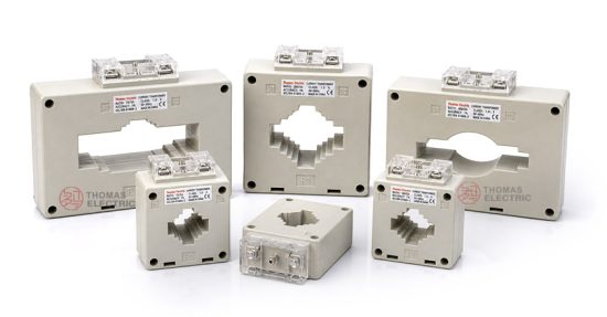
Product Shows
 Low-Voltage Plastic Case Current Transformer Thomas Electric")
Working Principle
Operating on Faraday’s law of electromagnetic induction, the transformer features a toroidal magnetic core through which the primary conductor passes. The magnetic flux generated by primary current induces proportional voltage in the secondary winding wound around the core, delivering standardized 5A output current through connected burden. The window-type construction allows the primary conductor (busbar or cable) to pass through the aperture without direct electrical connection to the CT.
System Application Position
- Low-Voltage Distribution: 0.66kV switchgear, motor control centers, and distribution panels
- Energy Metering: Revenue-grade and sub-metering electricity measurement systems
- Protection Circuits: Overcurrent and earth fault protection schemes
- Load Monitoring: Real-time current monitoring in industrial and commercial installations
- Power Quality Analysis: Current measurement for power factor correction and harmonic analysis
Structural Form Overview
Window-type (bushing) construction with epoxy resin insulated core provides superior electrical performance, moisture resistance, and mechanical strength. The through-conductor design enables flexible installation in confined switchgear environments while maintaining excellent electrical clearance. Compact footprint suitable for space-constrained low-voltage distribution equipment.
Model Designation
 Low-Voltage Plastic Case Current Transformer Thomas Electric")
Model Code Explanation
- BH — Current transformer model series designation
- 0.66 — Voltage class: 0.66 kV (660V low-voltage system)
- (I) — Indoor installation configuration
- 30/40/50/60/80/100/120 — Rated primary current in Amperes
Primary Current Selection
Available primary current ratings: 30A, 40A, 50A, 60A, 80A, 100A, and 120A. Selection depends on the feeder continuous load rating, expected operating range, and coordination with downstream protective devices. All variants share identical secondary current (5A) and mechanical envelope for simplified inventory and installation.
Service Conditions
The BH-0.66(I) series current transformers are designed for indoor operation under normal service conditions in low-voltage power distribution systems.
- Installation environment: Indoor installation only
- Altitude: Not exceeding 2000 m above sea level (higher altitude configurations available upon request)
- Ambient temperature: −5 °C to +40 °C
- Relative humidity: Daily average ≤ 95%, monthly average ≤ 90% (at +25 °C reference)
- Environmental conditions: Free from corrosive gases, explosive atmospheres, or conductive dust; no severe vibration or mechanical shock
- Operating frequency: 50 Hz or 60 Hz
Construction
Construction Design
- Structure: Window-type (bushing-type) for through-conductor installation
- Insulation: Epoxy resin insulated toroidal core
- Core: Ring-type magnetic core with optimized permeability
- Conductor passage: Central aperture for primary busbar or cable routing
- Enclosure: Protective housing with terminal access for secondary connections
The epoxy resin insulation system provides stable dielectric properties and resistance to moisture, contamination, and thermal aging for long-term indoor service in low-voltage distribution environments.
Windings & Terminal Marking
- Primary: Through-conductor (busbar or cable passing through CT aperture), no dedicated terminals
- Secondary terminals: K and L marking (or S1/S2 depending on configuration)
- Polarity: Directional arrow or polarity marking indicates current flow reference direction
Terminal markings follow standard CT polarity conventions per IEC 61869-2. Under normal operating conditions, current entering at the marked polarity point on the primary conductor produces current from K to L (or S1 to S2) on the secondary. Correct terminal identification shall be observed to ensure metering accuracy and protection directionality.
Technical Data
This section provides selection-oriented technical data for the BH-0.66(I) series window-type current transformer used in 0.66 kV class AC low-voltage distribution systems (50/60 Hz). Data shown below is intended for preliminary selection of accuracy class, rated burdens, and short-circuit withstand capability.
Definitions: Accuracy class indicates metering (0.5, 1.0) or protection (1) core performance. Rated output (VA) is the burden capacity per secondary core. Ith is the rated short-time thermal current (typically 1 s). Idyn is the rated dynamic current (peak).
Notation: Ith/Idyn values are based on system fault level and busbar/cable rating; acceptance shall be based on nameplate values and factory test report.
Data Reference
| Rated Primary Current (A) | Transformation Ratio | Accuracy Class | Rated Output (VA) | Typical Ith (kA, 1s) | Typical Idyn (kA peak) |
|---|---|---|---|---|---|
| 30 | 30/5 | 0.5, 1, or Protection 1 | 2.5, 5, 10 | 0.6 | 1.5 |
| 40 | 40/5 | 0.5, 1, or Protection 1 | 2.5, 5, 10 | 0.8 | 2.0 |
| 50 | 50/5 | 0.5, 1, or Protection 1 | 2.5, 5, 10 | 1.0 | 2.5 |
| 60 | 60/5 | 0.5, 1, or Protection 1 | 2.5, 5, 10 | 1.2 | 3.0 |
| 80 | 80/5 | 0.5, 1, or Protection 1 | 2.5, 5, 10 | 1.6 | 4.0 |
| 100 | 100/5 | 0.5, 1, or Protection 1 | 2.5, 5, 10 | 2.0 | 5.0 |
| 120 | 120/5 | 0.5, 1, or Protection 1 | 2.5, 5, 10 | 2.4 | 6.0 |
Standards & Normative References
| Standard | Title | Application |
|---|---|---|
| IEC 61869-1 | Instrument Transformers – Part 1: General Requirements | General requirements |
| IEC 61869-2 | Instrument Transformers – Part 2: Additional Requirements for Current Transformers | CT-specific requirements |
| GB/T 20840.1 | Instrument Transformers – Part 1: General Requirements | National standard (aligned with IEC 61869 framework) |
| GB/T 20840.2 | Instrument Transformers – Part 2: Current Transformers | National CT requirements (aligned with IEC 61869-2) |
| GB 1208-1997 | Current Transformers | National CT standard for legacy installations |
| IEC 60364 | Low-Voltage Electrical Installations | Installation requirements reference |
Factory Testing Compliance
- Routine tests per IEC 61869-2 / GB/T 20840.2 requirements (polarity verification, ratio verification, accuracy verification per specified class and burden)
- Dielectric tests per insulation coordination requirements
- Visual and dimensional inspection including terminal marking and workmanship conformity
- Type tests (on representative samples): temperature rise, short-time withstand, accuracy limit verification
Installation & Dimensions
 Low-Voltage Plastic Case Current Transformer Thomas Electric")
 Low-Voltage Plastic Case Current Transformer Thomas Electric")
- The transformer shall be mounted in accordance with switchgear manufacturer’s specifications and dimensional drawings.
- Primary conductor (busbar or cable) shall pass centrally through the CT aperture to ensure uniform flux distribution.
- For multi-turn primary configurations, ensure all turns pass through the aperture in the same direction.
- Secondary terminals shall be accessible for wiring to meters, relays, or monitoring devices.
- Adequate clearance shall be maintained for heat dissipation and maintenance access in accordance with IEC 60364 or local electrical code.
Typical Dimensions
Window aperture: Sized to accommodate primary busbar or cable cross-section (consult dimensional drawing for specific models)
Overall envelope: Compact design suitable for space-constrained low-voltage switchgear installation
Mounting: Bolt-down or clip-mount configuration depending on switchgear design
Safety Notes
- Secondary circuit must never be left open when the transformer is energized, as dangerous high voltage may appear across the secondary terminals.
- During inspection, testing, or maintenance, the secondary circuit shall be short-circuited before disconnecting any instruments or wiring.
- One point of the secondary circuit should be reliably grounded in accordance with IEC 61869-2 and local electrical safety standards.
- All installation and maintenance work shall comply with applicable low-voltage electrical safety regulations (IEC 60364 series or equivalent).
- Verify CT polarity and secondary wiring before energizing to ensure proper metering and protection operation.
Ordering Information
When placing an order, the required configuration shall be specified according to the facility electrical design, applicable standards, and project technical specification. The following parameters shall be clearly stated for technical confirmation and production release:
- Rated primary current (30A, 40A, 50A, 60A, 80A, 100A, or 120A)
- Transformation ratio (e.g., 100/5)
- Accuracy class (metering: 0.5 or 1.0 / protection: 1)
- Rated burden (VA) for the secondary core
- Short-circuit withstand requirements: Ith (1 s) and Idyn (peak) based on system fault level
- Window aperture dimensions (if non-standard busbar/cable size)
How to Select
1: Determine rated primary current (Ip) based on feeder continuous load rating, expected operating range, and allowable overload margin (typically 1.2× to 1.5× continuous load).
2: Select accuracy class based on application: 0.5 for revenue metering, 1.0 for sub-metering or indication, Protection 1 for overcurrent relays.
3: Confirm rated burden (VA) for the secondary circuit based on connected meter/relay burden and wiring resistance (use 5A × total circuit impedance to calculate burden).
4: Verify short-circuit withstand capability (Ith/Idyn) against the low-voltage system prospective short-circuit current at the installation point.
If project-specific requirements apply (e.g., extended temperature range, special aperture dimensions, dual-core configuration, specific terminal arrangement, or required certificates), specify them at the ordering stage. Special configurations shall be confirmed by technical agreement prior to production.
FAQs
Q1: How to select CT ratio and rated primary current for a low-voltage distribution panel?
A: Select rated primary current from feeder continuous load with appropriate margin (typically 1.2–1.5×), then verify against low-voltage switchgear design and protection coordination. CT shall not saturate under maximum expected load conditions.
Q2: What is the difference between metering and protection accuracy classes in low-voltage CTs?
A: Metering classes (0.5, 1.0) ensure accurate measurement within normal operating range (typically up to 120% rated current). Protection class (1) maintains accuracy under fault conditions to ensure proper relay operation.
Q3: How to determine rated burden (VA) for 5A secondary circuits?
A: Rated burden (VA) shall cover total connected load including meter/relay consumption plus wiring resistance losses. Calculate as: Burden (VA) = 5A × (meter burden Ω + cable resistance Ω). Verify rated burden ≥ calculated burden.
Q4: What are the acceptance requirements for Ith and Idyn in low-voltage applications?
A: Ith (1 s) and Idyn (peak) shall meet or exceed the system prospective short-circuit current at the installation point. Acceptance is by nameplate rating and factory test report per IEC 61869-2.
Q5: Can multiple primary turns be used to modify the transformation ratio?
A: Yes. Passing the primary conductor through the CT aperture N times creates an effective ratio of (Ip × N)/5. For example, 100/5 CT with 2 primary turns becomes 50/5. Ensure all turns pass through in the same direction.
Q6: What are the mandatory secondary handling and grounding requirements?
A: Do not open-circuit CT secondary under energized primary. Short-circuit secondary before disconnecting meters. Ground one secondary terminal per IEC 61869-2 and local electrical code. Observe polarity markings for correct metering and protection directionality.
Q7: Which documents govern compliance for low-voltage CT installations?
A: Nameplate and factory test report are primary references. Installation shall comply with IEC 60364 (low-voltage installations) or local electrical code. Unit test certificates provide traceability to standards compliance.
Q8: What window aperture size is required for typical low-voltage busbars?
A: Standard models accommodate common busbar cross-sections used in 0.66kV distribution (e.g., 40×5mm, 60×8mm). Consult dimensional drawing or specify busbar dimensions at ordering for custom aperture requirements.