Product Overview
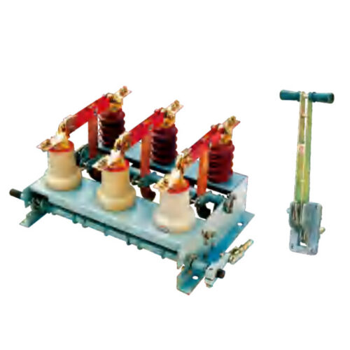
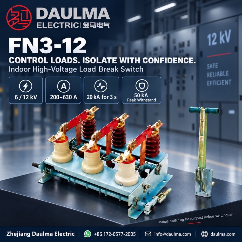
The FN3-12 and FN3-12R/S series are indoor high-voltage load break switches designed for 50 Hz AC systems operating at 6 kV or 12 kV. They provide reliable switching of load currents and support protection applications when used with compatible high-voltage fuses. Engineered for frequent operation with minimal maintenance, these switches integrate seamlessly into medium-voltage indoor switchgear panels and can be equipped with CS2 or CS3 manual operating mechanisms for enhanced safety and control.
Product Display
Model Designation
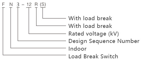
Model format: FN3-12 R(S)
- F: load break switch
- N: indoor application
- 3: design sequence number
- 12: rated voltage, kV
- R: with load breaking capability
- S: with integrated earth (grounding) switch
Service Conditions
- Ambient temperature: standard service conditions apply
- Altitude: 1000 m or less standard; consult the technical team for higher altitudes
- Humidity: non-condensing, per IEC 62271 practice
- Special requirements: custom configurations available upon request
Construction
The switch incorporates an RN3-type arc-extinguishing vacuum interrupter for reliable load current interruption. Terminal markings include P1/P2 for power input and output and S1/S2 for fuse connections where applicable.
The frame is arranged for compact indoor mounting with standardised interface dimensions for ease of integration into switchgear panels, and the CS2 or CS3 manual mechanism is linked to the switch shaft at the panel front.
Technical Data
| Parameter | Symbol | Value |
|---|---|---|
| System frequency | f | 50 Hz |
| Rated voltage | Ue | 6 kV / 12 kV |
| Rated current | In | 200 A / 400 A / 630 A |
| Rated short-time withstand current (3 s) | Isc | 20 kA |
| Rated peak withstand current | Ipk | 50 kA |
| Mechanical life | N | 2000 operations or more |
| Arc-extinguishing medium | — | Vacuum (RN3-type interrupter) |
| Operating mechanism | — | CS2 or CS3 manual mechanism |
Standards
The source page quotes humidity practice per IEC 62271 but no full standard number for the switch. The usual references for indoor high-voltage load break switches are IEC 62271-102 / IEC 60265-1 and GB/T 3804; confirm the applicable edition with the factory when ordering.
Installation & Dimensions
Installation Diagram
The FN3-12 series is designed for compact indoor mounting with standardised interface dimensions for ease of integration into switchgear panels. Verify panel cut-out dimensions and clearance requirements before installation, and ensure all circuits are de-energised during mounting and wiring.
| Dimension | Value (mm) |
|---|---|
| Overall height | 480 |
| Overall width | 260 |
| Overall depth | 190 |
| Mounting hole spacing, vertical | 320 |
| Mounting hole spacing, horizontal | 200 |
| Phase spacing | 150 |