FN5-12 (RDL) Indoor High-Voltage Load Break Switch - featured

FN5-12 (RDL) Indoor High-Voltage Load Break Switch

FN5-12 (RDL) Indoor Load Break Switch, 12 kV 630 A

  • 630 A rated and load breaking current at 12 kV
  • 20 kA short-time withstand current, 50 kA peak
  • Top-mounted fuse gives short-circuit protection
  • Closed, open and earthed operating positions
  • 1.3 kA rated transfer current on the fuse duty
  • 2000-cycle mechanical life for frequent switching

Product Overview

The FN5-12 (RDL) indoor high-voltage load break switch is engineered for dependable performance in 10 kV ring networks, distribution boxes and substations. It complies with IEC 420 and the 1990 edition of the high-voltage load break switch standards, and supports three operational positions: closed, open and earthed. Built for AC 50 Hz, 12 kV systems, the switch reliably breaks rated load currents and closes onto short-circuit currents; when used with a fuse it provides effective short-circuit fault interruption to safeguard downstream equipment.

Product Display
FN5-12 (RDL) Indoor High-Voltage Load Break Switch - display

FN5-12 (RDL) Indoor High-Voltage Load Break Switch - poster_display

Model Designation

FN5-12 (RDL) Indoor High-Voltage Load Break Switch - model

Model format: FN5-12 (RDL)

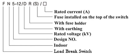
  • F: load break switch; N: indoor application
  • 5: design series number; 12: rated voltage, 12 kV
  • D: equipped with fuse at top
  • R: capable of load breaking
  • L: with earth (grounding) switch

Service Conditions

  • Altitude: not exceeding 1000 metres
  • Ambient temperature: maximum +40 °C, minimum -25 °C
  • Relative humidity: daily average 95% or less, monthly average 90% or less
  • Environment: free from conductive dust, corrosive gases, explosive media and excessive water vapour
  • Mechanical stress: no continuous or severe vibration or shock

Construction

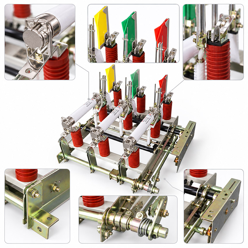
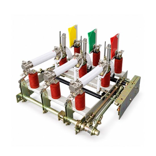
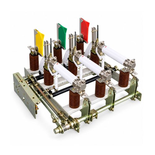
The FN5-12 (RDL) features a modular internal structure comprising a base frame, insulation supports, arc tube, damping equipment, moving and static contacts, arcing rod, guide plate, interruption mechanism, locking system, operating mechanism and an integrated earthing switch.

Terminal markings follow standard conventions: P1/P2 denote power-side terminals while S1/S2 indicate load-side terminals. The top-mounted fuse, indicated by D in the type code, provides the short-circuit protection of the feeder.

Technical Data

Name Unit Value
Rated voltage kV 12
Maximum operating voltage kV 12
Rated frequency Hz 50
Rated current A 630
Rated load breaking current A 630
5% rated load breaking current A 31.5
Rated short-circuit breaking current A 10
Rated moving contact current A 40
Rated transfer current kA 1.3
Rated short-time withstand current kA 20
Rated peak withstand current kA 50
Mechanical life cycle 2000
Selection note: standard parameters listed above can be customised; for specific application requirements contact the technical support team. Confirm a 12 kV, 50 Hz indoor system and verify the 630 A load duty against the feeder before ordering.

Standards

The switch complies with IEC 420 and the 1990 edition of the high-voltage load break switch and load break switchgear standards.

Technical note: standard parameters can be customised on request.

Installation & Dimensions

Installation Diagram
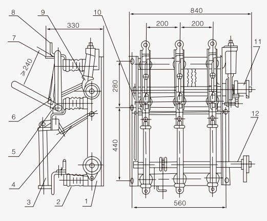
FN5-12 (RDL) Indoor High-Voltage Load Break Switch - installation

Installation requires secure mounting on a rigid support structure with proper clearance. Ensure alignment of the operating mechanism linkages and verify interlock functionality before energisation, and confirm the fixing-hole pattern and phase clearances against the outline drawing.

Dimension Value (mm)
Overall width (front view) 840
Base / panel mounting width 560
Phase (pole) spacing 200
Side-view depth 550
Upper frame height 280
Lower frame height 440
Safety notice: always de-energise and verify zero voltage before installation, maintenance or inspection. Ensure proper grounding and adherence to local electrical codes, and do not operate under load unless explicitly rated for load-breaking duty.

FAQs

The rated short-circuit breaking current is 10 A with a rated transfer current of 1.3 kA, while the switch withstands a short-time current of 20 kA and a peak of 50 kA. Short-circuit fault interruption above the transfer duty is provided by the top-mounted fuse coordinated with the switch.

Yes, provided relative humidity does not exceed a 95% daily average and a 90% monthly average, and the environment remains free from corrosive gases, conductive dust, explosive media and excessive water vapour. Verify the site conditions before installation.

The standard rated current and rated load breaking current are 630 A, with a 5% rated load breaking current of 31.5 A and a rated moving contact current of 40 A. Specify the exact load requirement during the inquiry stage.

D indicates the fuse equipped at the top of the switch, R the capability of load breaking and L the integrated earth (grounding) switch. Together with F for load break switch, N for indoor application, 5 for the design series and 12 for the rated voltage in kV, they form the full type designation.

It provides reliable load breaking up to 630 A with a 50 kA peak short-circuit making capacity, three operational positions of closed, open and earthed, and a modular structure with integrated earthing switch, which suits ring networks, distribution boxes and substations.

The modular internal structure comprises a base frame, insulation supports, arc tube, damping equipment, moving and static contacts, arcing rod, guide plate, interruption mechanism, locking system, operating mechanism and an integrated earthing switch. Terminal markings follow standard conventions: P1/P2 for power-side terminals and S1/S2 for load-side terminals.

Inquiry for FN5-12 (RDL) Indoor High-Voltage Load Break Switch:

Send your project requirements. Our team will reply with technical details and quotation.

Fast response Technical support OEM / ODM