Product Overview
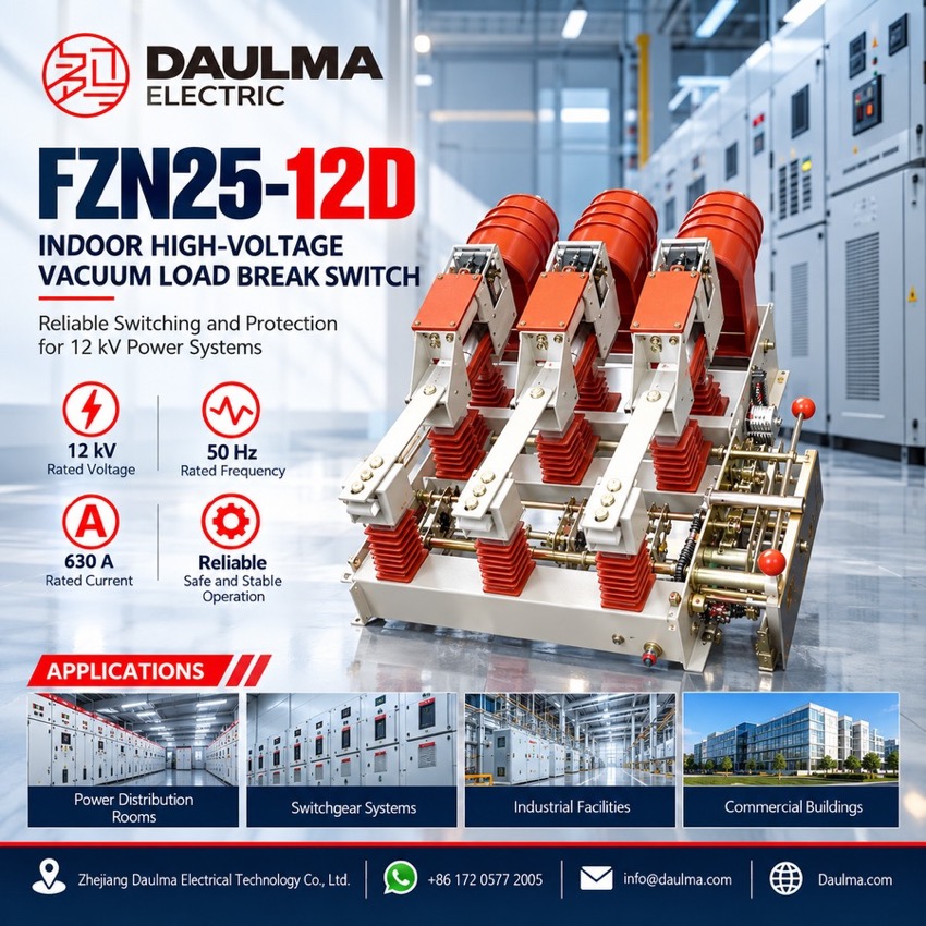
The FZN25-12D is an indoor three-phase vacuum load break switch for 50 Hz ring supply and terminal supply networks at 12 kV. The plain switch makes and breaks load and closed-loop current at 630 A, cable charging current at 10 A and no-load transformers up to 1250 kVA, while the fused FZRN25-12D combination unit clears any current up to its rated short-circuit breaking current of 31.5 kA. A direct-acting drive links the isolating gap to the vacuum arc chamber, so the chamber carries high voltage only during the instant of closing and opening, which keeps the unit small and light and gives breaking duty and visible isolation in one stroke. Earthing flaps interlocked with the earthing switch sit between the static contacts and the conducting cylinders, so the de-energised side is earthed before anyone works on the unit.
Product Display
Model Designation
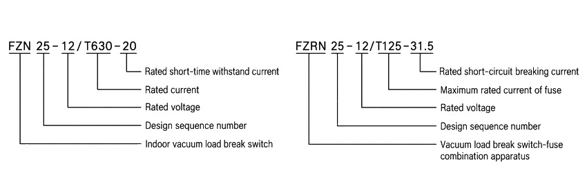
Model format: FZN25-12D/T 630-20 (load break switch) and FZRN25-12D/T 125-31.5 (switch-fuse combination unit)
- FZN: indoor vacuum load break switch; the added R marks the fuse-combination apparatus
- 25: design sequence number
- 12: rated voltage, kV
- D: with earthing switch
- T: with spring operating mechanism
- 630 / 125: rated current of the switch, or maximum rated current of the fuse, A
- 20 / 31.5: rated short-time withstand current, or rated short-circuit breaking current, kA
Service Conditions
- Ambient temperature: +40 °C upper, -25 °C lower
- Altitude: not more than 1000 m
- Relative humidity: daily average not more than 95%, monthly average not more than 90%
- Seismic intensity: not more than 8 degrees
- Site condition: no fire, explosion hazard, chemical corrosion or violent vibration
- Pollution level: II
Construction
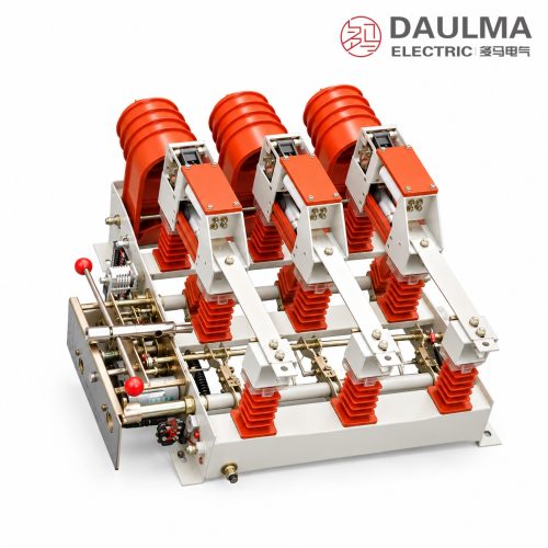
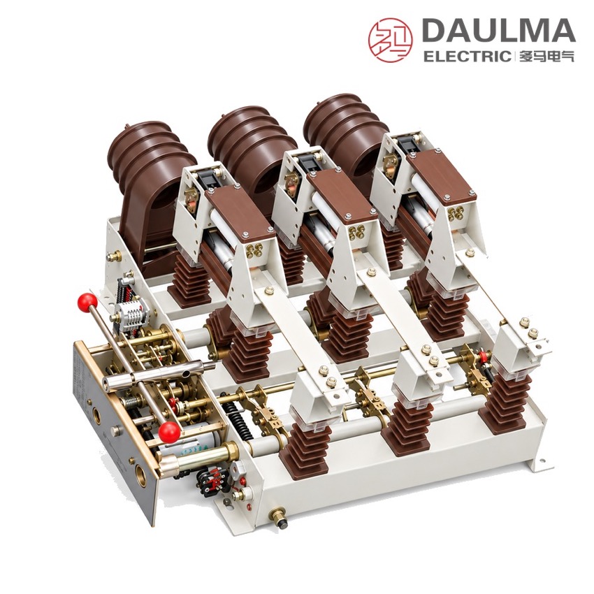
The three poles stand on a common frame. Each pole carries a static contact head at the rear, a vacuum arc chamber and a conducting cylinder with the moving contact, an insulation cover over the live part and red porcelain insulators to the frame. The operating mechanism at the front of the frame drives the poles through the energy storage shaft and the earthing shaft, and the front operating panel shows and selects the position.
The isolating gap and the vacuum chamber move together, so one stroke gives both the breaking duty and the visible isolation. The earthing switch works against the static earthing contact, and the earthing flaps between the static contacts and the conducting cylinders are interlocked with it, so the fuse compartment cannot be opened live.
Closing energy comes from a charged spring on the energy storage shaft, so contact speed is set by the mechanism and not by the operator. Energy can be stored by hand or from the control supply, which makes electric operation and remote signalling possible. In the combination unit the release device is worked by the striker of the blown SDLAJ-12 fuse, which needs only 2 to 5 J of striker output energy.
Technical Data
| No. | Item | Unit | FZN25-12D/T 630-20 | FZRN25-12D/T 125-31.5 |
|---|---|---|---|---|
| 1 | Rated voltage | kV | 12 | 12 |
| 2 | Rated frequency | Hz | 50 | 50 |
| 3 | Rated current | A | 630 | 125 |
| 4 | 1 min power-frequency withstand voltage | kV | Vacuum arc chamber gap 30; phase-to-earth and phase-to-phase 42; isolating gap 48 | Vacuum arc chamber gap 30; phase-to-earth and phase-to-phase 42; isolating gap 48 |
| 5 | Lightning impulse withstand voltage | kV | Phase-to-earth and phase-to-phase 75; isolating gap 85 | Phase-to-earth and phase-to-phase 75; isolating gap 85 |
| 6 | Rated peak withstand current | kA | 50 | — |
| 7 | Rated short-time withstand current, 4 s | kA | 20 | — |
| 8 | Rated active load breaking current | A | 630 | 125 |
| 9 | Rated closed-loop breaking current | A | 630 | 125 |
| 10 | Rated cable charging breaking current | A | 10 | 10 |
| 11 | No-load transformer breaking capacity | kVA | 1250 | 1250 |
| 12 | Rated short-circuit breaking current | kA | — | 31.5 |
| 13 | Rated transfer current and rated change-over current | A | — | 2000 |
| 14 | Fuse type | — | — | SDLAJ-12 |
| 15 | Striker output energy | J | — | 2–5 |
| 16 | Rated short-circuit making current | kA | 50 | 50 |
| 17 | Earthing switch rated peak withstand current | kA | 50 | 50 |
| 18 | Earthing switch rated short-time withstand current, 2 s | kA | 20 | 20 |
| 19 | Auxiliary circuit rated voltage | V | AC/DC 220 V, 110 V | AC/DC 220 V, 110 V |
| 20 | Mechanical life | operations | 1000 | 1000 |
Standards
The source page does not quote a standard number for this switch. The usual references for indoor high-voltage load break switches are IEC 62271-102 and GB/T 3804; confirm the applicable edition with the factory when ordering.
Installation & Dimensions
Installation Diagram
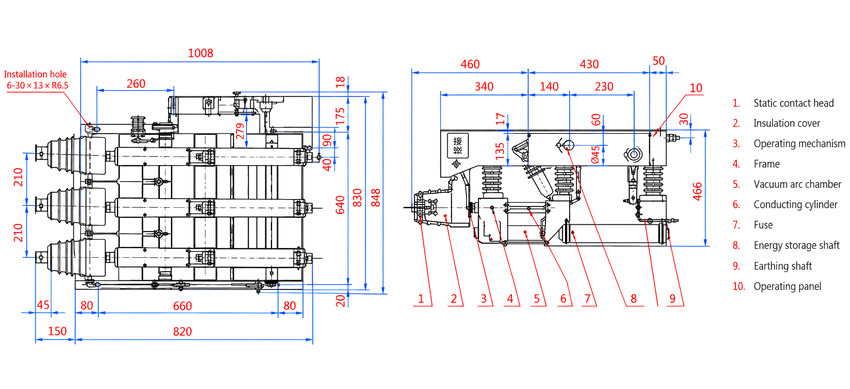
The unit is bolted to the cubicle frame through six 30 by 13 mm mounting slots. Before energisation, check the closed, open and earthed positions and the interlocks between the switch, the earthing switch and the fuse compartment on all three poles, fit the specified SDLAJ-12 fuse with its striker engaging the release device, and measure the main circuit resistance and the contact travel.
| Dimension | Value (mm) |
|---|---|
| Overall width (front view) | 1008 |
| Overall height | 848 |
| Depth (side view) | 466 |
| Mounting footprint over feet | 820 |
| Outer mounting hole centres | 660 |
| Pole centre pitch | 210 |
| Mounting slots | 6 × 30 × 13, R6.5 |