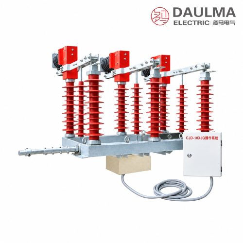
Product Overview
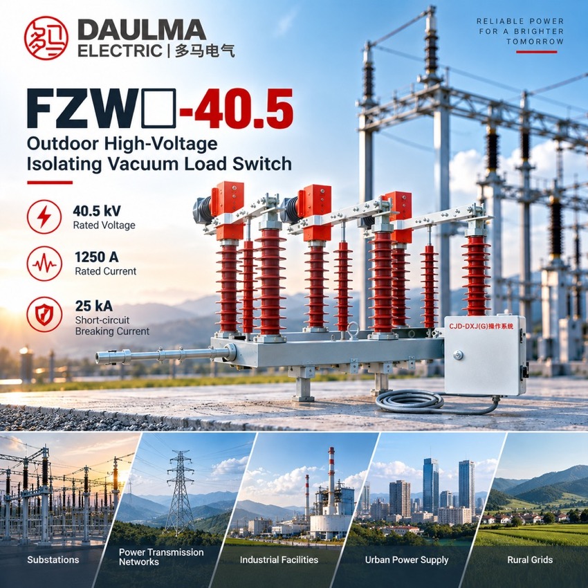
The FZW-40.5 is a three-pole outdoor vacuum load break switch developed for 40.5 kV, 50 Hz overhead distribution networks. It makes and breaks load current under normal operation and also breaks the capacitive charging current of overhead lines, cable lines and capacitor banks within a defined distance. Each pole combines a vacuum interrupter with a visible isolating gap, so load breaking and disconnecting are performed by one compact unit that provides sectioning, isolating, connecting and changeover functions for urban and rural networks, railways and petrochemical plants.
Product Display
Model Designation
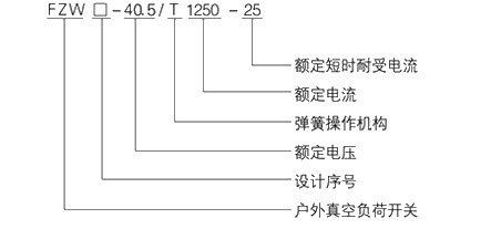
Model format: FZW□-40.5/1250-25
- FZW – outdoor vacuum load break switch
- □ – design sequence number
- 40.5 – rated voltage, kV
- T – spring operating mechanism
- 1250 – rated current, A
- 25 – rated short-time withstand current, kA
- Other current and withstand-current combinations are available on request
Service Conditions
- Altitude: not more than 2000 m
- Ambient temperature: -30 ℃ to +40 ℃
- Wind speed: not more than 35 m/s
- Relative humidity: daily average ≤ 95%, monthly average ≤ 90%
- No frequent severe vibration
Construction
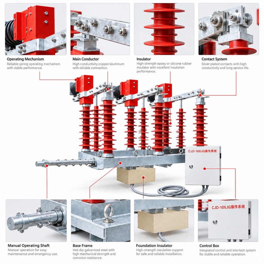
Three poles are carried on a galvanized steel frame with red composite insulator columns. Each pole pairs a vacuum interrupter with a serial isolating gap, giving visible isolation in the open position, and a side-mounted CJ□-10XJG cabinet houses the spring operating mechanism; the frame base suits both structure-mounted and pole-mounted installation.
Under load the arc is extinguished in the vacuum interrupters and the isolating blades then open to leave a visible safety gap. Type tests and long-term trial operation confirm high breaking capacity, long electrical endurance, suitability for frequent operation and low maintenance on feeder sectioning, isolation and supply-route changeover duty.
Technical Data
| No. | Item | Unit | Parameter |
|---|---|---|---|
| 1 | Rated voltage | kV | 40.5 |
| 2 | Rated frequency | Hz | 50 |
| 3 | Rated current | A | 1250 |
| 4 | Rated active load breaking current | A | 1250 |
| 5 | Rated closed-loop breaking current | A | 1250 |
| 6 | 5% rated active load breaking current | A | 62.5 |
| 7 | Rated cable charging breaking current | A | 25 |
| 8 | 1 min power-frequency withstand voltage (vacuum gap / phase-to-phase and phase-to-earth / isolation gap) | kV | 68/95/110 |
| 9 | Lightning impulse withstand voltage (phase-to-phase and phase-to-earth / isolation gap) | kV | 185/215 |
| 10 | Rated short-time withstand current (thermal stability) | kA | 25 |
| 11 | Rated short-circuit duration | s | 4 |
| 12 | Rated peak withstand current (dynamic stability) | kA | 63 |
| 13 | Rated short-circuit making current | kA | 63 |
| 14 | Mechanical life | operations | 10000 |
| 15 | Permissible contact wear of vacuum interrupter | mm | 0.6 |
| 16 | Manual operating torque | Nm | ≤300 |
Standards
The product conforms to GB 3804 and the applicable IEC standards for high-voltage load break switches, and the design is type tested and verified by long-term trial operation, confirming high breaking capacity, long electrical endurance, suitability for frequent operation and low maintenance.
Installation & Dimensions
Installation Diagram
Level the frame on a steel structure or pole platform with the base fully bolted, and connect the earthing terminal to the earth grid with a dedicated conductor. Check three-pole simultaneity, the contact travel of the vacuum interrupters and isolating blades, smooth charge and release of the spring mechanism, and manual operating torque within 300 Nm. Before energisation run the power-frequency withstand check on the main circuit and verify the terminal markings against the approved outline drawing.