Product Overview
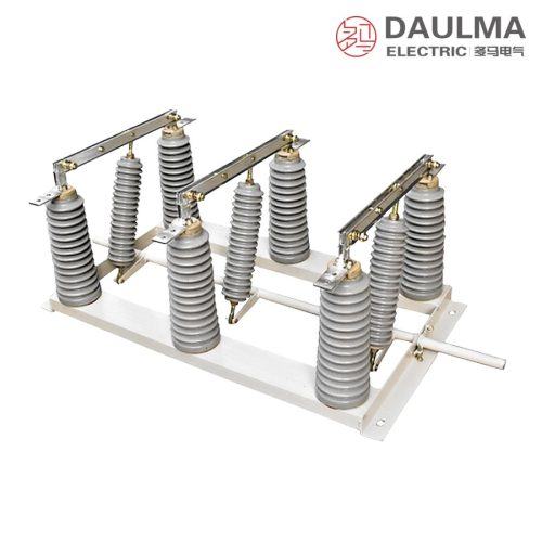
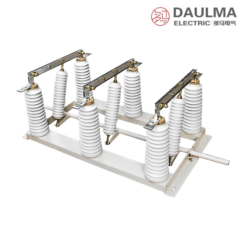
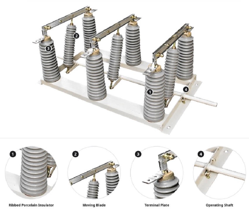
The GN27-40.5 is an indoor high-voltage AC disconnector for three-phase 50 Hz systems of the 35 kV class. Three poles on a common frame carry copper knife and contact systems on post insulators, coupled by a linkage shaft so all phases open together and give a visible isolating gap. It connects or transfers circuits under voltage but without load, is driven by a CS6-2 manual mechanism (CS6-1 on the D earthing-switch version) and is interlocked with the associated circuit breaker. Flat-mounted, C1 and C2 through-wall forms suit fixed indoor switchgear in distribution substations.
Product Display
Model Designation
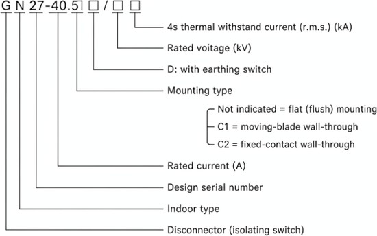
Model format: G N 27-40.5 □ / □ □
- G – disconnector
- N – place of use: indoor
- 27 – design sequence number
- 40.5 – rated voltage in kV
- □ – rated current in A
- / □ – mounting: none = flat-mounted; C1 = moving-knife through-wall; C2 = static-contact through-wall
- □ – 4 s thermal-stable current (r.m.s.) in kA
- D – with earthing switch (uses the CS6-1 mechanism)
Service Conditions
- Altitude: up to 1000 m
- Ambient temperature: not above +40 ℃ and not below -25 ℃
- Relative humidity: daily average not above 95%, monthly average not above 90%
- Water-vapour pressure: daily average not above 2.2 × 10⁻³ MPa, monthly average not above 1.8 × 10⁻³ MPa
- Site free from fire, explosion, corrosion of metals, harmful gases that damage insulation and conductive dust
Construction
Three poles are carried on a common frame, each with a copper knife and contact system on post insulators and coupled by a linkage shaft so that all three phases operate simultaneously. Opening the knives gives a clearly visible insulating gap for safe maintenance, and the disconnector is interlocked with the associated circuit breaker because it cannot break load or short-circuit current.
Operation is by a CS6-2 manual mechanism, or a CS6-1 mechanism where the D earthing-switch version is fitted. The range is offered flat-mounted for standard cubicles or with through-wall mounting – C1 brings the moving knife and C2 the static contact through the panel barrier – so the circuit can pass through the cubicle wall.
Technical Data
| Item | Unit | Value |
|---|---|---|
| Rated voltage | kV | 40.5 |
| System class | kV | 35 (three-phase, 50 Hz) |
| Rated frequency | Hz | 50 |
| Rated current | A | per technical agreement / nameplate |
| 4 s thermal-stable current (r.m.s.) | kA | per technical agreement / nameplate |
| Operating mechanism | — | CS6-2 manual (CS6-1 for D version) |
Standards
The source catalogue page quotes no specific product standard for the GN27-40.5. The disconnector is supplied to the order technical agreement and the equipment nameplate, which fix the rated current, the 4 s thermal-stable current and the insulation level for the chosen rating and mounting arrangement.
Installation & Dimensions
Installation Diagram
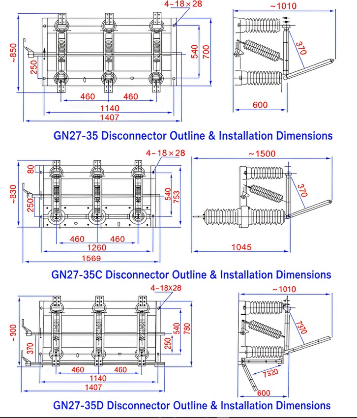
Mount the three poles on the common frame inside the cubicle at the specified phase spacing and fix the frame through the 4 × 18 × 28 mm mounting holes; for the through-wall versions pass the moving knife (C1) or the static contact (C2) through the panel opening. Couple the poles to the CS6-2 operating mechanism (CS6-1 on the D version), verify free travel, correct contact seating and the full visible break before energising, and bond the frame to the earth network. All outline dimensions are in mm; C denotes through-wall mounting and D the earthing-switch version.
| Item (mm) | GN27-35 | GN27-35C (through-wall) | GN27-35D (earthing switch) |
|---|---|---|---|
| Overall width (front) | 1407 | 1569 | 1407 |
| Overall height (front) | ≈ 850 | ≈ 830 | ≈ 900 |
| Depth (side) | 600 | 1045 | 600 |
| Phase spacing | 460 | 460 | 460 |
| Mounting holes | 4 × 18 × 28 | 4 × 18 × 28 | 4 × 18 × 28 |