Product Overview
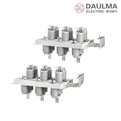
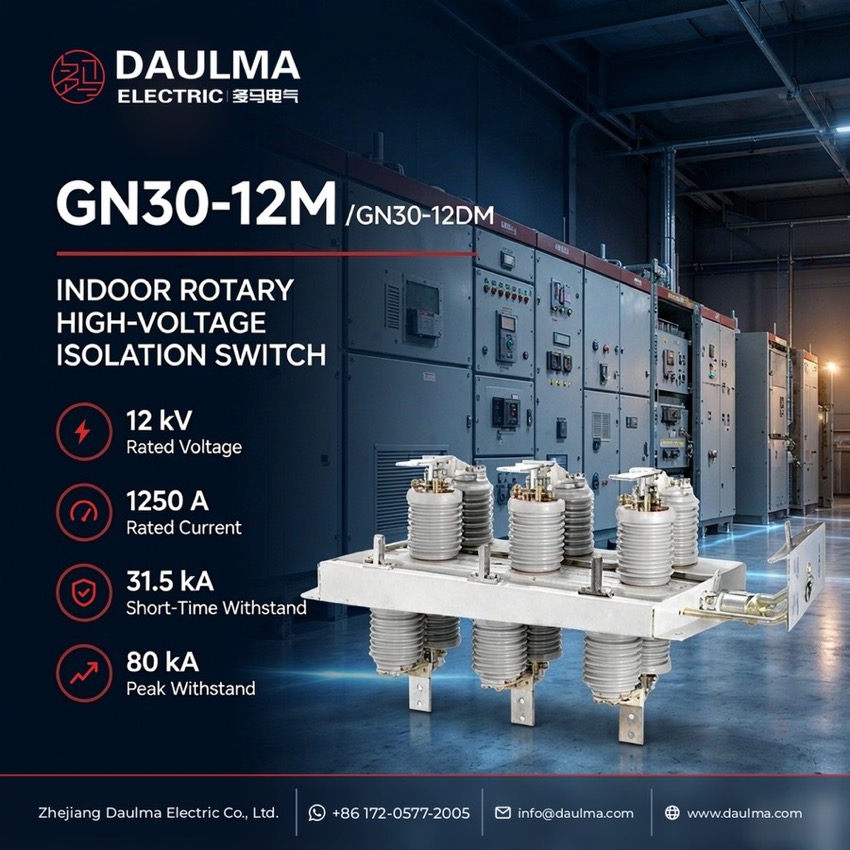
The GN30-12M is a panel-type indoor disconnector whose moving knife rotates between two insulator-and-contact sets on a shared three-phase frame, giving a visible isolating gap in 12 kV, 50 Hz metal-enclosed switchgear. Rated for networks of 10 kV and below, it connects, transfers or interrupts circuits that are live but unloaded, in four current grades from 400 A to 1250 A. The M suffix means the assembly sits behind the cubicle panel with the operating shaft brought through it, and adding the D earthing switch yields the GN30-12DM for maintenance earthing of the isolated side.
Product Display
Model Designation
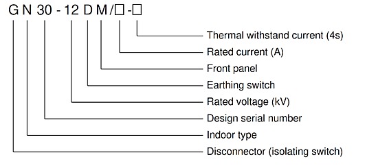
Model format: G N 30 – 12 D M / □ – □
- G – disconnector
- N – place of use: indoor
- 30 – design sequence number
- 12 – rated voltage, kV
- D – with earthing switch
- M – panel type, mounted behind the cubicle panel
- □ – rated current, A
- □ – thermal-stable current (4 s), kA
- Example: GN30-12DM/630-20 is the panel type with earthing switch at 630 A and 20 kA for 4 s
Service Conditions
- Altitude: not exceeding 1000 m
- Ambient air temperature: upper limit +40 °C, lower limit -10 °C
- Relative humidity: daily average not more than 95%, monthly average not more than 90%
- Seismic intensity: not above intensity 8
- Installation site free from severe dust, chemical corrosion and explosive substances, and free from frequent severe vibration
Construction
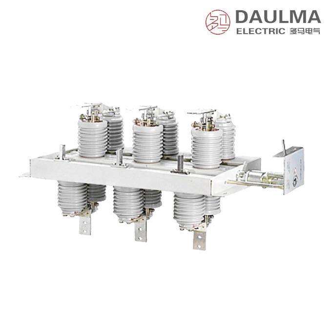
Each pole carries the rotating knife between two ribbed-porcelain insulator-and-contact sets fixed on the upper and the lower plane of one common three-phase base frame. The three poles are coupled to a single operating shaft driven by a manual mechanism at the panel, so the live parts stay behind the cubicle panel while the handle remains accessible from the front.
On GN30-12DM types the earthing knife is interlocked with the main knife and runs on its own shaft, so the isolated circuit can be earthed safely for maintenance. As a disconnector the unit has no load or short-circuit breaking capability and is operated only after the associated circuit breaker has opened the circuit.
Technical Data
| Item | Unit | 400 | 630 | 1000 | 1250 |
|---|---|---|---|---|---|
| Rated voltage | kV | 12 | 12 | 12 | 12 |
| Rated current | A | 400 | 630 | 1000 | 1250 |
| Thermal-stable current | kA | 12.5 | 20 | 31.5 | 31.5 |
| Thermal-stable time | s | 4 | 4 | 4 | 4 |
| Dynamic-stable current | kA | 31.5 | 50 | 80 | 80 |
Standards
The GN30 series conforms to GB 1985 for AC high-voltage disconnectors and earthing switches. The catalogue parameter table lists each current grade both as GN30-12M and as GN30-12DM, so the same rated data apply to the panel types with and without earthing switch.
Installation & Dimensions
Installation Diagram
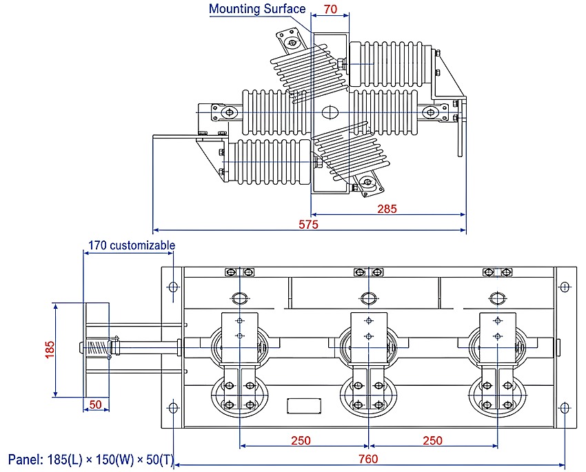
Bolt the three-pole frame to the cubicle mounting surface, fit the panel of the panel type over the frame and pass the operating shaft through it. Couple the poles to the manual mechanism and, on the DM types, the earthing knife to its own shaft. Before energising, check the free travel of the knives, the seating of the contacts and the full visible gap, and bond the frame to the earth network of the cubicle. The certified dimensional drawing issued with the order governs, since the values depend on the ordered rated current and on whether the earthing switch is fitted.
| Item | Unit | Value |
|---|---|---|
| Overall depth, side view | mm | 575 |
| From mounting surface to outer end, panel side | mm | 285 |
| From mounting surface, panel side | mm | 70 |
| Overall width, front view | mm | 760 |
| Phase spacing | mm | 250 + 250 |
| Panel, length x width x thickness | mm | 185 x 150 x 50 |
| Panel-side dimension, front view (customizable) | mm | 170 |