Product Overview
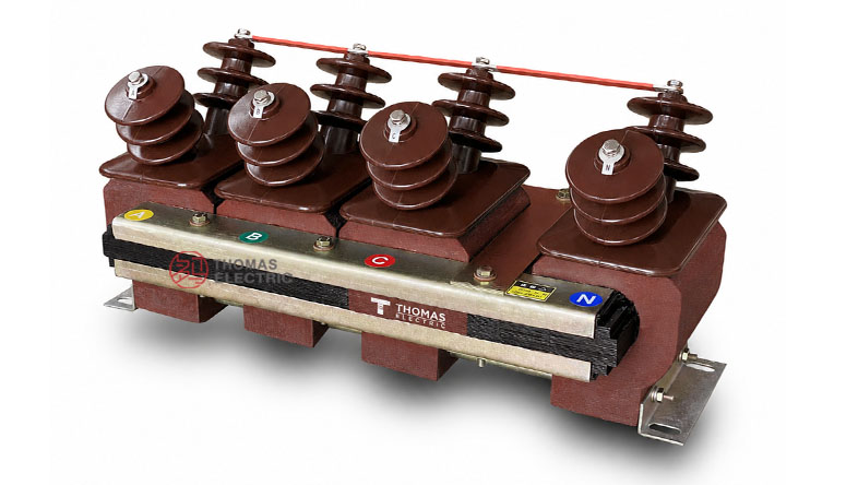
The JSZJK-3/6/10Q three-phase anti-ferroresonance voltage transformer is an indoor epoxy cast-resin voltage transformer designed for 3.6kV, 7.2kV and 12kV medium-voltage switchgear. It converts three-phase primary voltage into standardized secondary voltage signals for voltage metering, voltage monitoring, residual-voltage detection and relay protection.
This series is designed with an anti-ferroresonance structure for medium-voltage systems where voltage transformer resonance and grounding fault monitoring must be considered. The indoor cast-resin insulation structure is suitable for switchgear panels, metering compartments, distribution rooms and relay protection circuits.

Application Position
The JSZJK-3/6/10Q voltage transformer is normally installed in the voltage transformer compartment of indoor medium-voltage switchgear. It provides voltage signals to meters, protection relays, monitoring devices, grounding fault detection circuits and control equipment.
Main Applications
- 3.6kV, 7.2kV and 12kV indoor medium-voltage switchgear
- Three-phase voltage metering and voltage indication circuits
- Power monitoring and energy measurement systems
- Residual-voltage and grounding fault detection circuits
- Relay protection voltage input circuits
- Medium-voltage systems requiring anti-ferroresonance voltage transformer design
Key Specifications
| Item | Specification |
|---|---|
| Model series | JSZJK-3Q / JSZJK-6Q / JSZJK-10Q |
| Product type | Three-phase anti-ferroresonance voltage transformer |
| Insulation structure | Indoor epoxy cast-resin insulation |
| Installation | Indoor |
| Rated voltage class | 3.6kV, 7.2kV and 12kV |
| Rated frequency | 50Hz or 60Hz |
| Ambient temperature | -25°C to +40°C |
| Secondary winding configuration | Single secondary winding or two secondary winding groups according to model |
| Accuracy class | 0.2, 0.5, 1, 3P, 6P and combined metering/protection configurations |
| Limit output | 500VA or 600VA according to winding configuration |
| Standards | GB20840.3-2013, IEC61869-3:2011 and project-specific requirements |
Application Fit
Suitable For
- Indoor 3.6kV, 7.2kV and 12kV medium-voltage switchgear
- Three-phase voltage measurement and voltage monitoring circuits
- Grounding fault detection and residual-voltage protection applications
- Relay protection systems requiring stable secondary voltage signals
- Projects where anti-ferroresonance voltage transformer design is specified
Not Recommended For
- Outdoor exposed installation without a suitable enclosure
- Low-voltage systems outside the medium-voltage design range
- Applications requiring oil-immersed voltage transformer construction
- Special voltage ratios, secondary winding arrangements or accuracy classes without technical confirmation
Model Comparison
| Model | Voltage Class | Typical Use | Selection Note |
|---|---|---|---|
| JSZJK-3Q | 3.6kV | Three-phase voltage metering and residual-voltage protection | Select for 3.6kV indoor switchgear with 3.6/25/40kV insulation level |
| JSZJK-6Q | 7.2kV | 7.2kV switchgear metering, monitoring and protection | Select according to single or dual secondary winding requirement |
| JSZJK-10Q | 12kV | 12kV switchgear metering, monitoring and protection | Select according to 12/42/75kV insulation level and secondary output configuration |
Technical Structure
| Component | Description |
|---|---|
| Three-phase core and winding system | Provides three-phase voltage transformation and secondary signal output |
| Anti-ferroresonance structure | Designed to reduce the risk of ferroresonance in applicable medium-voltage systems |
| Epoxy cast-resin insulation | Indoor dry-type insulation structure for compact switchgear installation |
| Primary terminals | A, B, C and N side primary terminals arranged according to the wiring diagram |
| Secondary terminal groups | Available with one secondary winding group or two secondary winding groups |
| Mounting base | Base-mounted structure for indoor cabinet installation |
Model Designation
The JSZJK model code can be interpreted as follows:
| Code | Meaning |
|---|---|
| J | Voltage transformer |
| S | Three-phase structure |
| Z | Epoxy cast-resin insulation |
| J | Voltage transformer structure / design code |
| K | Anti-ferroresonance design code |
| 3 / 6 / 10 | Model voltage code corresponding to 3.6kV, 7.2kV and 12kV voltage classes |
| Q | Product variant code according to manufacturer specification |
Technical Data
The following technical data is based on the JSZJK-3Q, JSZJK-6Q and JSZJK-10Q product sample, converted into international medium-voltage class expression for export product pages. One voltage transformer can only be supplied with one selected accuracy class and corresponding rated output combination.
| Type | Voltage
Ratio |
Accuracy
Class and Output |
Limit
Output (VA) |
Rated
Insulation Level (kV) |
|---|---|---|---|---|
| JSZJK-3Q | 3000/√3 / 100/√3 / 100 | 0.2/6P(3P)—20/100 0.5/6P(3P)—40/100 1/6P(3P)—80/100 |
600 | 3.6/25/40 |
| JSZJK-6Q | 6000/√3 / 100/√3 / 100 | 7.2/30/60 | ||
| JSZJK-10Q | 10000/√3 / 100/√3 / 100 | 12/42/75 | ||
| JSZJK-6Q | 6000/√3 / 100/√3 / 100/3 | 0.2/0.2/6P(3P)—15/15/100 0.2/0.5/6P(3P)—15/20/100 0.5/0.5/6P(3P)—20/20/100 |
500 | 7.2/30/60 |
| JSZJK-10Q | 10000/√3 / 100/√3 / 100/3 | 0.2/0.2/6P(3P)—15/15/100 0.2/0.5/6P(3P)—15/20/100 0.5/0.5/6P(3P)—20/20/100 |
12/42/75 | |
| JSZJK-6Q | 6000/√3 / 100/√3 / 220/√3 / 100 | 0.2/3/6P(3P)—15/400/100 0.5/3/6P(3P)—20/400/100 |
7.2/30/60 | |
| JSZJK-10Q | 10000/√3 / 100/√3 / 220/√3 / 100 | 0.2/3/6P(3P)—15/400/100 0.5/3/6P(3P)—20/400/100 |
12/42/75 |
Technical notes:
- Rated frequency: 50Hz or 60Hz.
- Ambient temperature: -25°C to +40°C.
- The product complies with GB20840.3-2013, IEC61869-3:2011 and special project requirements.
- One voltage transformer can only be supplied with one selected accuracy class and corresponding rated output.
- If the required parameters exceed the listed range, they should be confirmed by agreement between manufacturer and purchaser.
Installation and Dimensions

The JSZJK-3/6/10Q series should be installed according to the approved outline drawing, wiring diagram and switchgear layout. The product is a three-phase integrated structure with multiple primary bushings and secondary terminal groups.
Overall Dimension Reference
| Item | Dimension / Specification |
|---|---|
| Overall length | 688 mm |
| Main mounting length | 643 mm |
| Phase spacing reference | 208 ±3 mm, 150 ±3 mm, 150 ±3 mm |
| Overall width | 280 mm |
| Side reference width | 168 mm |
| Side bushing spacing | 195 mm |
| Overall height | 295 mm |
| Mounting bolts | 8-M8 |
| Approximate weight | 81.6 kg |
Terminal and Wiring Notes
- Primary terminals and secondary terminals should be connected according to the approved wiring diagram.
- Different diagrams are available for one secondary winding group or two secondary winding groups.
- Residual-voltage and protection secondary circuits should be connected according to the project protection scheme.
- Terminal markings must be verified before commissioning.
- The transformer should be firmly mounted and the grounding connection should be checked before energizing.
Compliance and Testing
The JSZJK-3/6/10Q series is designed for indoor medium-voltage voltage transformer applications. The provided product sample refers to GB20840.3-2013 and IEC61869-3:2011, together with customer-specific requirements.
Typical Routine Tests
- Visual inspection and nameplate verification
- Ratio verification
- Polarity and terminal marking check
- Accuracy test at specified rated burden
- Power-frequency withstand voltage test
- Insulation resistance test
- Secondary winding and residual-voltage winding verification
- Wiring group verification when required by the project
Engineering Notes
- Select JSZJK-3Q, JSZJK-6Q or JSZJK-10Q according to the required 3.6kV, 7.2kV or 12kV switchgear class.
- Confirm whether the project requires one secondary winding group or two secondary winding groups.
- Do not exceed the rated output corresponding to the selected accuracy class.
- For residual-voltage or grounding fault protection, confirm the secondary voltage ratio and protection class.
- Check the 81.6 kg approximate weight, mounting length and switchgear space before installation.
- For special ratios, special protection classes or environmental conditions, technical confirmation is required before ordering.
Selection Guide
How to Select the Correct JSZJK Model
Select JSZJK-3Q for 3.6kV switchgear, JSZJK-6Q for 7.2kV switchgear and JSZJK-10Q for 12kV switchgear. The rated insulation level and voltage ratio should match the switchgear rated voltage and protection scheme.
How to Select Secondary Winding Configuration
Use a single secondary winding group when only one metering/protection output is required. Use two secondary winding groups when independent metering and protection circuits, or residual-voltage protection functions, must be connected separately.
How to Select Accuracy Class and Rated Output
Use 0.2 or 0.5 accuracy class for metering circuits. Use 3P or 6P protection classes for relay protection or residual-voltage detection. The rated output should be higher than the total connected secondary burden.
How to Confirm Anti-Ferroresonance Requirement
Anti-ferroresonance voltage transformer design is used where the system requires improved resistance to voltage transformer ferroresonance. Confirm the grounding method, protection scheme and switching conditions before final selection.
Ordering Information
Please provide the following information when ordering or requesting a quotation:
- Product model: JSZJK-3Q, JSZJK-6Q or JSZJK-10Q
- Rated voltage ratio and secondary winding configuration
- Rated frequency: 50Hz or 60Hz
- Required accuracy class and rated output
- Residual-voltage or protection winding requirement
- Rated insulation level
- Installation dimensions or switchgear layout requirements
- Applicable standard or project specification
- Quantity
- Special requirements for drawings, test reports, certificates, nameplate language, packaging or shipping