Product Overview
The LZZBJ9-12A1 / LZZBJ9-12A2 current transformer is an indoor, full-enclosed, epoxy cast-resin insulated, support-structure single-phase current transformer designed for medium-voltage AC power systems with rated voltage up to 12kV. It is used to provide isolated secondary current signals for current measurement, electric energy metering, feeder monitoring, and relay protection in indoor switchgear systems.
This product is developed for IEC-oriented 11KV, 12kV applications and is suitable for 3kV–12kV indoor distribution systems with rated frequency of 50Hz or 60Hz. The A1 and A2 versions are treated as mechanical or structural variants under the same LZZBJ9-12A platform. Final selection should be based on switchgear layout, mounting space, primary terminal arrangement, and project drawing requirements.
Product Type
| Item | Specification |
|---|---|
| Product name | Indoor Full-Enclosed Cast-Resin Current Transformer |
| Model series | LZZBJ9-12A1 / LZZBJ9-12A2 |
| Product structure | Full-enclosed, support structure, single-phase, epoxy cast-resin type |
| Rated voltage class | 11KV, 12kV class, suitable for indoor 3kV–12kV medium-voltage systems |
| Rated insulation level | 12/42/75kV |
| Rated frequency | 50Hz / 60Hz |
| Rated secondary current | 5A or 1A |
| Installation location | Indoor switchgear and distribution equipment |
| Typical applications | Current measurement, energy metering, relay protection, feeder monitoring, switchgear instrumentation |
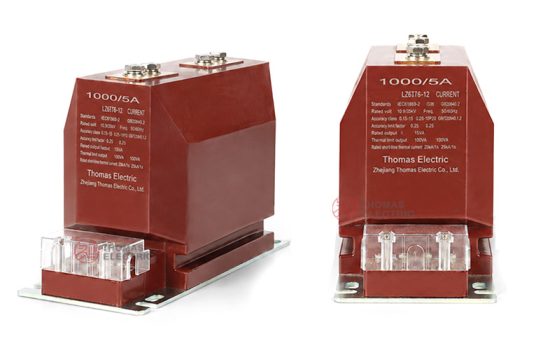
Product Display


Main Applications
- 3kV–12kV indoor medium-voltage distribution systems
- 11KV, 12kV metal-clad switchgear, feeder cabinets, and circuit breaker panels
- Current measurement and electric energy metering circuits
- Relay protection circuits for feeders, transformers, motors, and distribution lines
- SCADA, power monitoring, and energy management systems
- Industrial substations, commercial distribution rooms, and utility distribution panels
Key Technical Features
- 11KV, 12kV full-enclosed cast-resin insulation: The epoxy resin casting structure provides stable insulation performance, mechanical strength, and protection against indoor humidity and contamination.
- Support structure design: The transformer combines current transformation and mechanical support functions for compact installation in medium-voltage switchgear.
- A1 / A2 variant options: A1 and A2 are provided as structural variants for different mounting layouts, terminal positions, and cabinet integration requirements.
- Metering and protection cores: The product can be configured for measuring accuracy classes and protection classes such as 10P according to project requirements.
- 1A or 5A secondary output: Compatible with common energy meters, protection relays, monitoring devices, and switchgear secondary systems.
- Short-circuit withstand design: Short-time thermal current and dynamic current ratings are selected according to current ratio, nameplate data, and system fault level.
Working Principle
The LZZBJ9-12A1 / LZZBJ9-12A2 current transformer operates according to electromagnetic induction. The primary current flowing through the primary conductor generates magnetic flux in the magnetic core. The secondary winding then outputs a proportional current signal to the connected meter, relay, or monitoring device. The epoxy cast-resin insulation system provides electrical isolation between the primary medium-voltage circuit and the secondary low-voltage measurement circuit.
For metering applications, the secondary output must maintain the specified ratio and phase accuracy within the rated burden. For relay protection applications, the protection core must provide a reliable current signal under fault-current conditions and coordinate with the protection relay settings.
Model Designation

The model code can be interpreted as follows:
| Code | Meaning |
|---|---|
| L | Current transformer |
| Z | Indoor type |
| Z | Cast-resin insulated / fully enclosed structure |
| B | Protection configuration available for metering and relay applications |
| J | Reinforced design / enhanced insulation structure |
| 9 | Design sequence / product platform |
| 12 | Rated voltage class: 12kV |
| A1 / A2 | Mechanical structure variants for different switchgear installation layouts |
Technical Data
| Item | Specification |
|---|---|
| Rated voltage | 12kV and below |
| Rated insulation level | 12/42/75kV |
| Rated frequency | 50Hz / 60Hz |
| Rated secondary current | 5A or 1A |
| Rated primary current | 10A to 3150A reference range, subject to project specification and nameplate |
| Accuracy class | 0.2S, 0.2, 0.5, 10P or combined metering/protection classes according to order |
| Rated output | 10VA, 15VA, 20VA or project-specific configuration at cosφ = 0.8 |
| Metering security factor | FS 5 or FS 10 according to metering core specification |
| Protection accuracy limit factor | ALF 10, 15 or 20 according to protection core specification |
| Power frequency withstand voltage | 42kV / 1min according to insulation level reference |
| Rated dynamic current | Selected according to ratio and project fault-current requirement |
| Installation type | Indoor support-type mounting in medium-voltage switchgear |
| Applicable standard | IEC 60044-1; IEC 61869-1 / IEC 61869-2 or GB/T 20840 may be used according to project requirement |
Windings and Terminal Marking

The LZZBJ9-12A1 / LZZBJ9-12A2 current transformer can be supplied with single-core or multi-core secondary winding configurations according to the metering and protection requirements of the project. Typical secondary terminals are marked as 1S1 / 1S2 for the first secondary core and 2S1 / 2S2 for the second secondary core when a combined metering and protection configuration is used.
| Terminal Marking | Function | Application Note |
|---|---|---|
| P1 / P2 | Primary terminals | The reference primary current direction is normally defined from P1 to P2. |
| 1S1 / 1S2 | First secondary winding | Usually used for metering, measurement, or the first specified secondary core. |
| 2S1 / 2S2 | Second secondary winding | Usually used for relay protection or an additional secondary circuit when required. |
| Terminal cover / secondary terminal box | Secondary wiring protection | Terminal layout and cover structure shall be confirmed according to the approved drawing. |
Terminal markings follow standard current transformer polarity conventions. Under normal operating conditions, correct terminal identification shall be observed to ensure metering accuracy, relay direction judgment, and protection performance. The secondary circuit of a current transformer must not be left open when the primary circuit is energized.
Rated Current, Accuracy and Short-Circuit Withstand Reference
| Rated Current
Ratio (A) |
Accuracy Class
Combination |
Rated
Output (VA) |
FS | ALF | 1s Short-Time
Thermal Current |
Rated
Dynamic Current |
|---|---|---|---|---|---|---|
| 10–200/5 | 0.2S / 0.2S, 0.2S
/ 0.5, 0.2S / 10P, 0.5 / 10P, 0.2S / 0.5 / 10P, 0.2 / 0.5 / 10P |
10 / 15 / 15 | 5 or 10 | 10 / 15 / 20 | 150 × I1n | 375 × I1n |
| 300/5 | 10 / 15 / 20 | 31.5kA | 80kA | |||
| 400/5 | 10 / 15 / 20 | 31.5kA | 80kA | |||
| 500/5 | 10 / 15 / 20 | 40kA | 100kA | |||
| 600/5 | 10 / 15 / 20 | 50kA | 125kA | |||
| 800/5 | 10 / 15 / 20 | 63kA | 125kA | |||
| 1000/5 | 10 / 15 / 20 | 80kA | 160kA | |||
| 1200–1500/5 | 10 / 15 / 20 | 80kA | 160kA | |||
| 1500–2000/5 | 10 / 15 / 20 | 100kA | 160kA | |||
| 2000–3150/5 | 10 / 15 / 20 | 130kA | 160kA |
Note: Accuracy class combination, FS and ALF are shared parameters for the listed current ratios. The data above is for preliminary technical selection. Final current ratio, accuracy class, rated burden, FS, ALF, Ith, Idyn, insulation level, and test requirements shall be confirmed according to the nameplate, approved drawing, and factory test report.
Service Conditions
- Installation location: indoor medium-voltage switchgear
- Rated voltage: 12kV and below
- Rated frequency: 50Hz / 60Hz
- Ambient temperature: -5°C to +40°C
- Altitude: ≤1000m under standard service conditions
- The installation environment should be free from severe vibration, conductive dust, corrosive gas, explosive medium, heavy contamination, and abnormal condensation.
- For high altitude, coastal, humid, high dust, high pollution, or special cabinet conditions, technical confirmation is required before ordering.
Standards and Compliance
The LZZBJ9-12A1 / LZZBJ9-12A2 current transformer is designed for indoor medium-voltage current transformer applications. It can be supplied according to IEC 60044-1, and project requirements may also specify IEC 61869-1, IEC 61869-2, GB/T 20840.1, or GB/T 20840.2. Routine tests, dielectric tests, accuracy verification, polarity check, and partial discharge requirements should be confirmed according to the final technical agreement.
Installation and Dimensions

The LZZBJ9-12A1 / LZZBJ9-12A2 series is designed for indoor switchgear installation. The A1 and A2 versions should be selected according to switchgear mounting space, primary terminal geometry, secondary terminal direction, phase-to-ground clearance, and maintenance access. Final outline dimensions and mounting holes shall be confirmed by approved drawings before cabinet design or batch production.
Available Structure and Overall Dimensions
| Item | Selection Note |
|---|---|
| Mechanical variants | LZZBJ9-12A1 and LZZBJ9-12A2 |
| Mounting type | Indoor support-structure installation |
| Primary terminals | P1 / P2 terminal arrangement according to approved drawing |
| Secondary terminals | 1S1 / 1S2 and optional 2S1 / 2S2 according to core configuration |
| Structure selection | A1 / A2 variant selected according to switchgear structure, mounting holes, and terminal direction |
| Drawing confirmation | Final outline and installation dimensions shall be confirmed before switchgear production |
Installation and Safety Notes
- Confirm the model, voltage class, current ratio, secondary current, accuracy class, burden, FS/ALF, and short-circuit withstand requirement before installation.
- Check that the switchgear mounting space, busbar connection, phase clearance, and grounding arrangement meet the approved drawing.
- Connect primary and secondary terminals according to terminal markings and the project wiring diagram.
- The secondary circuit of a current transformer must not be left open when the primary circuit is energized.
- During meter or relay maintenance, short-circuit the CT secondary circuit before disconnecting any secondary wiring.
- One point of the secondary circuit should be grounded according to the project specification and local electrical safety requirements.
- Installation and maintenance shall be performed by qualified medium-voltage electrical personnel.
Ordering Information
Please provide the following information when ordering or requesting a quotation:
- Product model: LZZBJ9-12A1 or LZZBJ9-12A2
- Rated voltage and system voltage level
- Rated primary current / current ratio
- Rated secondary current: 1A or 5A
- Metering and protection accuracy class combination
- Rated burden for each secondary core
- FS and ALF requirements if specified
- Short-circuit withstand requirement: Ith and Idyn
- Insulation level, partial discharge requirement, and applicable standard
- Switchgear type, installation layout, terminal direction, and required outline drawing
- Quantity, certificate, routine test report, labeling, and packaging requirements
Selection Guidelines
- Confirm system voltage: Select this CT for indoor medium-voltage systems rated up to 12kV.
- Confirm mechanical variant: Choose LZZBJ9-12A1 or LZZBJ9-12A2 according to switchgear mounting layout and terminal orientation.
- Confirm current ratio: Select rated primary current according to feeder load, continuous operating current, and protection range.
- Select secondary current: Use 5A for common short secondary wiring layouts and 1A where lower secondary burden or longer wiring distance is required.
- Specify metering and protection cores: Define each secondary core separately with accuracy class, burden, FS, or ALF.
- Verify rated burden: The total burden of meters, relays, and secondary cables shall not exceed the rated output of each core.
- Check short-circuit withstand: Ith and Idyn shall meet or exceed the prospective short-circuit current and peak current of the switchgear system.
- Confirm testing and documentation: Specify routine test certificates, partial discharge test, type test documents, and applicable standards if required.