Product Overview
The LZZBJ9-12D1 / LZZBJ9-12D2 current transformer is an indoor epoxy cast-resin current transformer designed for 11kV and 12kV class medium-voltage switchgear. It is used for current measurement, electric energy metering, feeder monitoring, and relay protection in AC power systems. The D1 and D2 versions can be written as one product family because they share the same 12kV insulation platform, similar application range, and metering/protection configuration logic, while the final model is selected according to current ratio, secondary winding groups, terminal layout, and cabinet drawing.
This page is intended to combine the existing LZZBJ9-10 A/B/C product logic with the newly supplied D1/D2 catalogue data. The older A/B/C page uses the LZZBJ9 indoor cast-resin CT platform for metering and protection, with 1A/5A secondary output, epoxy insulation, short-circuit withstand ratings, and IEC/GB standard positioning. For this product, the content should be differentiated by focusing on the D-type compact enclosed cast-resin body, multi-secondary winding groups, and 11kV / 12kV class international product positioning.
The product has a rated insulation level of 12/42/75kV. It can be configured with 5A or 1A secondary current, metering accuracy such as 0.2S and 0.5S, and protection class such as 5P20. Typical winding combinations include 0.2(S)/5P20, 0.5(S)/5P20, and 0.2(S)/0.5(S)/5P20/5P20.
Product Type
| Item | Specification |
|---|---|
| Product name | Indoor Epoxy Cast-Resin Current Transformer |
| Model series | LZZBJ9-12D1 / LZZBJ9-12D2 |
| Structure | Indoor enclosed epoxy cast-resin structure with top primary terminals and lower secondary terminal block |
| Voltage class | 11kV and 12kV class indoor medium-voltage systems |
| Rated insulation level | 12/42/75kV |
| Rated frequency | 50Hz; 60Hz available by project confirmation |
| Rated secondary current | 5A or 1A |
| Rated primary current | 50A to 2000A reference range according to catalogue data |
| Secondary winding groups | 1S / 2S / 3S / 4S according to ordered configuration |
| Typical application | Current measurement, energy metering, relay protection, feeder monitoring |
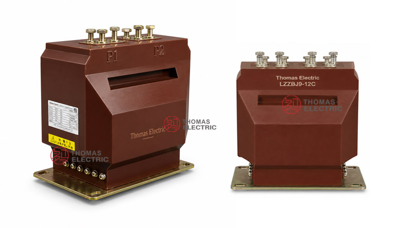
Product Display

The LZZBJ9-12D1 / D2 series uses a compact rectangular cast-resin body with top primary terminals and a lower secondary terminal block. The front opening and multi-terminal layout make it suitable for switchgear where metering and protection circuits must be separated within a compact CT body. The D1 and D2 variants should be selected according to the cabinet outline, current ratio, secondary winding quantity, rated output, and short-circuit withstand requirements.
Applications
- 11kV and 12kV class indoor medium-voltage switchgear
- Metering cabinets, incoming panels, outgoing feeder panels, and distribution switchboards
- Current measurement and electric energy metering circuits
- Relay protection circuits requiring 5P20 protection performance
- Multi-core CT applications requiring metering and protection outputs in one body
- OEM switchgear projects requiring compact D-type indoor CT installation
Features
- D1 / D2 combined product family: The two variants are grouped into one page to avoid duplicate SEO content while keeping clear model selection.
- 12kV class insulation design: The 12/42/75kV insulation level supports IEC-oriented 11kV and 12kV class switchgear projects.
- Multi-secondary winding options: 1S, 2S, 3S and 4S secondary groups can be configured for metering, measurement, protection and backup protection circuits.
- Metering and protection integration: Typical combinations include 0.2(S)/5P20, 0.5(S)/5P20 and 0.2(S)/0.5(S)/5P20/5P20.
- Compact epoxy cast-resin body: The enclosed resin structure provides insulation strength, mechanical stability and moisture resistance for indoor switchgear.
- Engineering-oriented selection: Current ratio, burden, terminal grouping, Ith/Idyn and cabinet layout should be checked together before final order.
Principle
The LZZBJ9-12D1 / D2 current transformer operates according to electromagnetic induction. Primary current flows through the primary conductor path and produces magnetic flux in the internal magnetic core. The secondary windings output proportional 5A or 1A current signals to meters, protection relays, energy metering devices or monitoring systems.
For metering cores, ratio accuracy and phase displacement must remain within the selected accuracy class and rated burden. For protection cores, 5P20 performance must provide reliable secondary output under fault-current conditions. Each secondary winding group should be assigned to a clear function before production.
Model Designation
| Code | Meaning |
|---|---|
| L | Current transformer |
| Z | Indoor type / cast-resin insulated structure reference |
| ZB | Epoxy cast-resin current transformer series |
| J | Reinforced or structural design reference |
| 9 | Design sequence / product platform |
| 12 | 12kV voltage class |
| D1 / D2 | D-type mechanical or secondary-winding configuration variants for 12kV indoor applications |
Technical Data
| Item | Specification |
|---|---|
| Rated voltage class | 11kV and 12kV class indoor systems |
| Rated insulation level | 12/42/75kV |
| Rated frequency | 50Hz; 60Hz by agreement |
| Rated secondary current | 5A or 1A |
| Rated primary current | 50A, 75A, 100A, 150A, 200A, 250A, 300A, 400A, 630A, 1500A, 1600A, 2000A |
| Secondary winding groups | 1S / 2S / 3S / 4S according to ordered configuration |
| Accuracy class combinations | 0.2(S)/5P20, 0.5(S)/5P20, 0.2(S)/0.5(S)/5P20/5P20 |
| Rated output | 0.2(S): 10VA; 0.5S: 15VA; 0.5: 15VA; 5P20: 20VA reference |
| Short-time thermal current | 21kA to 80kA reference range depending on primary current |
| Rated dynamic current | 52.5kA to 200kA reference range depending on primary current |
| Ambient temperature | -5°C to +40°C |
| Applicable standards | IEC 61869-2, GB20840.2-2014; legacy IEC 60044-1 / GB1208 references by project agreement |
Selection Table
The following selection table is reorganized from the catalogue data for website use. Long headers and long accuracy cells are split into multiple lines to improve responsive display.
| Rated
Primary Current (A) |
Short-Time
Thermal Current Ith / 1s |
Dynamic
Current Idyn Peak |
Accuracy Class
Combination |
Secondary
Output (VA) |
|---|---|---|---|---|
| 50 | 21kA | 52.5kA | 0.2(S) / 5P20 0.5(S) / 5P20 0.2(S) / 0.5(S) / 5P20 / 5P20 |
0.2(S): 10VA 0.5S: 15VA 0.5: 15VA 5P20: 20VA |
| 75 | 22kA | 55kA | ||
| 100, 150 | 40kA | 78kA | ||
| 200 | 37.8kA | 94.5kA | ||
| 250 | 40kA | 100kA | ||
| 300 | 50.4kA | 126kA | ||
| 400–630 | 63kA | 130kA | ||
| 1500, 1600 | 63kA | 130kA | ||
| 2000 | 80kA | 200kA |
Note: The table is for preliminary product-page selection. Final current ratio, secondary current, rated output, thermal current, dynamic current, terminal grouping, insulation test and accuracy class shall be confirmed by the nameplate, approved drawing and factory test report.
D1 / D2 Selection
| Variant | Recommended Use | Engineering Note |
|---|---|---|
| LZZBJ9-12D1 | Standard D-type indoor cast-resin CT configuration | Recommended when the switchgear layout matches the D1 outline and terminal arrangement. |
| LZZBJ9-12D2 | Alternative D-type configuration for different project requirements | Use when the customer drawing, mounting layout or secondary-core grouping requires the D2 variant. |
| D1 / D2 combined page | Website SEO and product family organization | Use one page for both variants to avoid duplicate content and show clear selection logic. |
Dimensions
| Item | Engineering Note |
|---|---|
| Structure | Compact rectangular cast-resin body with top primary terminals and lower secondary terminal block. |
| Primary terminals | Top P1 / P2 terminal arrangement; confirm busbar or cable lug connection by drawing. |
| Secondary terminals | Lower multi-terminal block for 1S / 2S / 3S / 4S winding groups. |
| Mounting base | Bottom mounting plate; fixing hole positions must follow the approved drawing. |
| D1 / D2 outline | Final dimensions and installation layout shall be confirmed by the selected D1 or D2 drawing. |
Terminals
The primary terminals are normally marked P1 and P2. Secondary terminal groups may be marked as 1S1 / 1S2, 2S1 / 2S2, 3S1 / 3S2 and 4S1 / 4S2. Each group should be assigned to a clear circuit function such as metering, measurement, protection or backup protection.
| Terminal | Function | Application Note |
|---|---|---|
| P1 / P2 | Primary terminals | Used for primary current direction and polarity reference. |
| 1S1 / 1S2 | First secondary winding | Usually assigned to metering or measurement circuit. |
| 2S1 / 2S2 | Second secondary winding | Can be assigned to protection or measurement according to project design. |
| 3S1 / 3S2 | Third secondary winding | Used where additional protection or monitoring output is required. |
| 4S1 / 4S2 | Fourth secondary winding | Used in multi-core configurations requiring independent secondary circuits. |
| Grounding point | Protective grounding | One point of the secondary circuit should be grounded according to project practice. |
Service Conditions
- Installation location: indoor medium-voltage switchgear
- Rated voltage: 11kV and 12kV class systems
- Rated frequency: 50Hz; 60Hz by agreement
- Ambient temperature: -5°C to +40°C
- Indoor environment should be free from conductive dust, corrosive gas, explosive medium, heavy pollution and abnormal condensation.
- For high humidity, coastal, high altitude or heavy-pollution sites, insulation coordination and creepage distance should be confirmed before ordering.
Standards and Compliance
For new international projects, the LZZBJ9-12D1 / D2 current transformer should be specified according to IEC 61869-2 current transformer requirements and GB20840.2-2014 where GB documentation is required. Older catalogue references such as IEC 60044-1 and GB1208 can be retained only as legacy references where required by the customer or tender document.
Installation and Dimensions

The LZZBJ9-12D1 / D2 is intended for indoor switchgear installation. Before cabinet production, confirm primary terminal spacing, secondary terminal grouping, mounting base holes, busbar clearance, phase-to-ground distance, wiring access and maintenance space. Because D1 and D2 may differ in outline and internal terminal configuration, the final drawing must match the nameplate model and ordered ratio.
Safety Notes
- Confirm voltage class, insulation level, current ratio, secondary current, accuracy class, rated burden and protection class before production.
- Check primary terminal spacing, busbar clearance, mounting holes, secondary terminal access and grounding position before switchgear assembly.
- Connect primary and secondary terminals according to polarity marks and approved wiring diagram.
- The CT secondary circuit must not be open-circuited while primary current is flowing.
- Before disconnecting meters or relays, short-circuit the secondary circuit with an approved shorting device.
- One point of the secondary circuit should be grounded according to project electrical safety practice.
- Installation and commissioning shall be performed by qualified medium-voltage electrical personnel.
Ordering Info
- Product model: LZZBJ9-12D1 or LZZBJ9-12D2
- Voltage class: 11kV or 12kV class
- Rated primary current and rated secondary current: 5A or 1A
- Secondary winding quantity: 1S / 2S / 3S / 4S
- Accuracy class combination and rated output for each secondary winding
- Protection class requirement: 5P20 or project-specific protection class
- Rated short-time thermal current and rated dynamic current
- Mounting drawing, terminal grouping, wiring diagram and switchgear layout
- IEC standard requirement, routine test report, certificate, label language and packaging requirement
Selection Guide
- Use one product page: Combine LZZBJ9-12D1 and LZZBJ9-12D2 into one product family page to avoid duplicate content.
- Confirm voltage class: Use 11kV and 12kV class wording for international projects, then verify 12/42/75kV insulation level.
- Select current ratio: Choose the rated primary current according to feeder load, metering range and protection setting.
- Define secondary groups: Confirm whether the project needs 1S, 2S, 3S or 4S secondary winding groups.
- Assign core functions: Use 0.2S or 0.5S for metering, and 5P20 for protection circuits.
- Verify withstand rating: Check Ith and Idyn against the switchgear fault level.
- Approve drawings: Confirm D1 or D2 outline, terminal grouping, mounting base and cabinet clearance before production.