Product Overview
The LZZBJ9-35/250-II / LZZB8-35 indoor epoxy cast-resin current transformer is a fully enclosed support-type current transformer designed for 35kV / 36kV / 40.5kV indoor medium-voltage power systems. It is used for current measurement, energy metering and relay protection in AC networks with rated frequency of 50Hz or 60Hz. The product adopts epoxy resin cast insulation, with the primary winding, secondary winding and magnetic core sealed inside the resin body to provide high insulation strength, moisture resistance and mechanical stability for indoor switchgear applications.
This page is positioned for the LZZBJ9-35/250-II and LZZB8-35 35kV-class indoor support-type CT platform. In the model code, 250 refers to the epoxy casting body width / product body width of 250mm, which is an important structural size for switchgear matching, insulation clearance and cabinet layout. Compared with smaller 10kV or 24kV indoor CTs, this product is designed for a higher insulation level of 40.5/95/185kV, higher switchgear voltage class, larger insulation body and multi-winding metering/protection combinations. It is suitable for air-insulated switchgear, indoor distribution cabinets and high-altitude indoor service conditions up to 3000m by project design reference.
Product Type


| Item | Specification |
|---|---|
| Product name | Indoor Epoxy Cast-Resin Current Transformer |
| Models | LZZBJ9-35/250-II / LZZB8-35 |
| Installation condition | Indoor |
| Structure | Fully enclosed support-type / pillar-type epoxy resin cast structure |
| Cast body width | 250mm reference, represented by “250” in the model code |
| Application | Current measurement, energy metering and relay protection |
| System voltage class | 35kV / 36kV / 40.5kV |
| Rated insulation level | 40.5/95/185kV |
| Rated frequency | 50Hz or 60Hz |
| Rated secondary current | 5A or 1A |
| Typical installation | Air-insulated switchgear, indoor distribution cabinet and power measurement panel |
Model Explanation

- L: Current transformer.
- Z: Support-type / pillar-type current transformer structure.
- Z: Epoxy resin casting insulation.
- B: Current transformer series with metering and protection winding options.
- J: Reinforced / enhanced structure design, usually used for protection-capable CT platforms.
- 9: Design sequence / product platform code.
- 35: 35kV class product platform, suitable for 35kV, 36kV and 40.5kV systems.
- 250: Epoxy casting body width, meaning the product cast-resin body width is 250mm.
- II: Structure version code
Applications
- 35kV, 36kV and 40.5kV indoor medium-voltage power systems
- Air-insulated switchgear and indoor distribution cabinets
- Current measurement for incoming and outgoing feeder circuits
- Energy metering and power measurement panels
- Relay protection for feeders, transformers and bus sections
- Industrial substations, utility substations and power distribution rooms
- High-altitude indoor applications up to 3000m by design reference
- Projects requiring a 250mm cast body width for cabinet layout and insulation coordination
Features
- 250mm cast body width: The “250” in the model code represents the epoxy casting body width / product body width, making cabinet matching and layout control clearer.
- 35kV-class insulation platform: Rated insulation level of 40.5/95/185kV for 35kV / 36kV / 40.5kV indoor systems.
- Fully enclosed resin body: Primary winding, secondary winding and core are sealed inside the cast-resin insulation body.
- Support-type structure: Designed for indoor switchgear fixation, stable mechanical support and convenient cabinet integration.
- Measurement and protection cores: Supports separate metering and protection windings, including single-ratio and double-ratio wiring schemes.
- High burden and high current options: Typical project configurations may include 300/5A or high-current options such as 2500A with 0.2S / 5P20 and 50VA according to technical agreement.
- Moisture-resistant insulation: Epoxy resin casting improves insulation stability in indoor power distribution rooms.
- High-altitude suitability: Can be specified for indoor service conditions up to 3000m where project insulation coordination is confirmed.
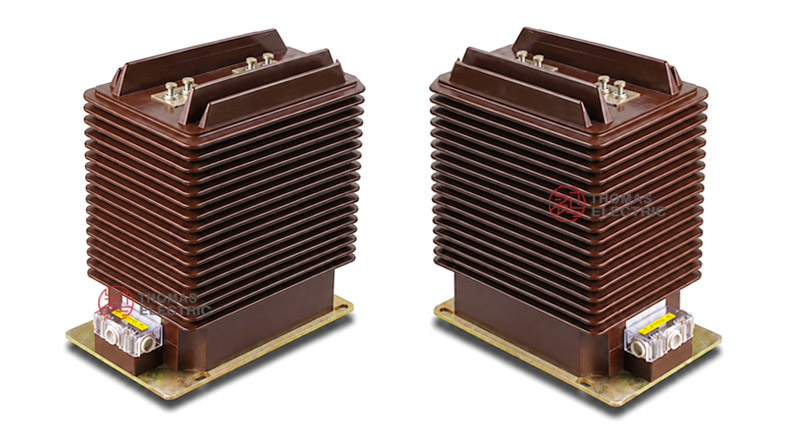
Structure Overview
The LZZBJ9-35/250-II / LZZB8-35 current transformer adopts epoxy resin cast insulation and a totally enclosed support-type structure. The primary outlet terminals are identified as P1 and P2. The secondary terminal groups are marked according to the winding arrangement, such as 1S1, 1S2, 2S1, 2S2, or extended forms such as 1S3 and 2S3 for double-current-ratio products.
The product is designed for indoor switchgear installation. The 250mm cast body width should be checked together with cabinet width, conductor position, terminal clearance, secondary wiring space and installation hole position. The final outline drawing and wiring diagram must be approved before production.
Operating Principle
The current transformer converts the primary current in a 35kV / 36kV / 40.5kV circuit into a standardized secondary current, normally 5A or 1A. The secondary current is supplied to energy meters, measuring instruments, protection relays or monitoring devices. This allows safe current measurement and protection control without direct electrical connection to the high-voltage primary circuit.
For metering applications, the CT should maintain ratio error and phase displacement within the selected accuracy class and rated burden. For protection applications, the protection winding must provide reliable secondary output under fault-current conditions. Current ratio, secondary current, accuracy class, rated burden, short-time thermal current and dynamic current must therefore be selected together according to the switchgear design and the system short-circuit level.
Technical Data
| Parameter | Specification |
|---|---|
| Models | LZZBJ9-35/250-II / LZZB8-35 |
| Product type | Indoor epoxy cast-resin current transformer |
| Cast body width | 250mm reference |
| System voltage class | 35kV / 36kV / 40.5kV |
| Rated insulation level | 40.5/95/185kV |
| Rated frequency | 50Hz or 60Hz |
| Rated secondary current | 5A or 1A |
| Power-frequency withstand voltage | Primary to secondary and earth: 95kV / 1min reference |
| Secondary power-frequency withstand voltage | Secondary to secondary and earth: 3kV / 1min reference |
| Lightning impulse withstand voltage | 185kV reference for 40.5kV insulation level |
| Ambient temperature | -15°C to +40°C reference; daily average not more than +30°C |
| Altitude | Not exceeding 3000m reference for high-altitude indoor service |
| Humidity condition | 24h average relative humidity not exceeding 95% reference |
| Contamination severity | Class II reference for indoor service condition |
| Applicable standards | IEC 61869-1, IEC 61869-2, GB/T 20840.1, GB/T 20840.2; legacy IEC 60044-1 / GB1208 / JJG 1021 references by agreement |
Selection Table
The following selection table is organized for website display. Long table headings and accuracy-class cells are split into multiple lines to reduce overflow in responsive product pages. Final values shall be confirmed by the approved drawing, nameplate and test report.
| Rated
Primary |
Accuracy
Class |
Rated
Output |
Short-Time ThermalCurrent |
Rated
Dynamic |
|---|---|---|---|---|
| 50 | 0.2 / 0.2 0.2 / 0.5 0.5 / 0.5 0.2 / 5P20 0.5 / 5P20 0.2S / 5P20 |
0.2: 15VA 0.5: 25VA 5P20: 50VA |
3kA | 7.5kA |
| 75 | 0.2: 15VA 0.5: 25VA 5P20: 50VA |
5kA | 12.5kA | |
| 100 | 0.2: 15VA 0.5: 25VA 5P20: 50VA |
8kA | 20kA | |
| 200, 300, 400 | 0.2: 15VA 0.5: 25VA 5P20: 50VA |
20kA | 50kA | |
| 600 | 0.2: 15VA 0.5: 25VA 5P20: 50VA |
31.5kA | 80kA | |
| 800, 1000, 1200, 1500, 1600 | 0.2 / 0.5 / 5P20 0.2S / 0.5 / 5P20 5P20 / 5P20 |
0.2: 15VA 0.5: 25VA 5P20: 50VA |
40kA | 100kA |
| 2500 | 0.2S / 5P20 0.2 / 5P20 0.5 / 5P20 |
50VA typical for protection winding | By agreement | By agreement |
Note: Customized current ratio, accuracy class, rated output and thermal / dynamic current parameters can be manufactured according to user requirements and technical agreement.
Wiring Diagram

The product can support single-current-ratio and double-current-ratio secondary wiring arrangements. The actual wiring shall follow the approved terminal diagram supplied with the product.
| Wiring Type | Terminal Marking | Application Note |
|---|---|---|
| Single current ratio | 1S1–1S2 for measurement winding 2S1–2S2 for protection winding |
Common arrangement for independent metering and relay protection outputs. |
| Double current ratio | 1S1–1S2 / 1S1–1S3 2S1–2S2 / 2S1–2S3 |
Small current ratio and high current ratio are selected by different secondary terminal combinations. |
| Example | P1–P2 primary side 1S1–1S2, 2S1–2S2 or 1S1–1S3, 2S1–2S3 secondary side |
For example, 50/100/5A may use different secondary terminals for 50/5A and 100/5A output selection. |
Wiring note: For double-current-ratio CTs, small current ratio and high current ratio must not be wired at the same time. Unused terminals should remain open according to the approved wiring instruction, while the active secondary circuit must never be left open during primary current operation.
Operating Conditions
- Installation: Indoor installation for 35kV / 36kV / 40.5kV switchgear and distribution systems.
- Rated frequency: 50Hz or 60Hz.
- Ambient temperature: -15°C to +40°C reference; daily average temperature not more than +30°C.
- Altitude: Does not exceed 3000m for high-altitude design reference.
- Humidity: 24h average relative humidity not exceeding 95% reference.
- Contamination severity: Class II reference for indoor service condition.
- Mechanical condition: No severe shake or bump at the installation site.
- Air quality: Ambient air should not be significantly polluted by dust, smoke, corrosive gases, vapours or salt.
Installation and Dimensions

The LZZBJ9-35/250-II / LZZB8-35 is installed inside 35kV-class switchgear or indoor distribution cabinets. Because the 250mm code represents the casting body width, cabinet matching should focus on body width, primary terminal spacing, secondary terminal box access, required insulation clearance and conductor layout. The base shall be fixed according to the approved outline drawing, and the secondary terminal box must remain accessible after cabinet assembly.
| Installation Item | Recommended Check Point |
|---|---|
| Cast body width | Confirm 250mm product body width against cabinet space and insulation layout. |
| Mounting base | Confirm base dimensions, fixing holes and support strength before installation. |
| Primary terminals | Check P1 / P2 direction, conductor connection method and insulation clearance. |
| Secondary terminal box | Reserve access space for wiring, testing, inspection and sealing. |
| Switchgear clearance | Confirm phase-to-phase and phase-to-ground clearance inside the cabinet. |
| Grounding | Ground one point of the secondary circuit according to the project grounding design. |
| Drawing confirmation | Use the approved outline drawing and terminal diagram for final production and installation. |
Windings & Terminal Marking
The primary outlet terminals are identified as P1 and P2. Secondary winding terminals are marked according to the number of secondary outputs, such as 1S1 / 1S2 for the first secondary winding and 2S1 / 2S2 for the second secondary winding. For double-current-ratio CTs, extended terminals such as 1S3 and 2S3 may be used.
| Terminal | Function | Application Note |
|---|---|---|
| P1 / P2 | Primary terminals | Used for primary current direction and polarity reference. |
| 1S1 / 1S2 | First secondary winding | Usually assigned to metering or measurement circuit. |
| 2S1 / 2S2 | Second secondary winding | Usually assigned to relay protection circuit. |
| 1S3 / 2S3 | Extended ratio terminals | Used for double-current-ratio products according to approved wiring diagram. |
| Grounding point | Secondary circuit grounding reference | One point of the secondary circuit should be grounded according to project practice. |
Standards and Compliance
For international product pages, the LZZBJ9-35/250-II / LZZB8-35 should be specified according to IEC 61869-1 and IEC 61869-2. GB-based documentation can refer to GB/T 20840.1 and GB/T 20840.2. Older catalogue references such as IEC 60044-1, GB1208 and JJG 1021 may be retained for comparison or tender compatibility, but modern product documentation should use IEC 61869 and GB/T 20840 series as the preferred standard language.
Safety Notes
- Confirm voltage class, rated insulation level, current ratio, secondary current, accuracy class and rated output before installation.
- Confirm that the 250mm cast body width matches cabinet space, insulation distance and terminal access requirements.
- Check that the selected CT matches the switchgear insulation distance and system short-circuit level.
- Verify P1 / P2 polarity and secondary terminal marking before connecting meters, relays or test equipment.
- For double-ratio CTs, confirm the correct secondary terminal group before energizing.
- Ensure the CT is firmly fixed in the cabinet and that all primary conductor connections are tightened according to project requirements.
- Ground one point of the secondary circuit according to the switchgear grounding design.
- The CT secondary circuit must not be open-circuited while primary current is flowing.
- Before disconnecting meters, relays or test devices, short-circuit the active secondary circuit with an approved shorting device.
- Keep the epoxy resin surface clean and dry to reduce tracking and insulation risk.
- Do not use the CT in environments with severe condensation, corrosive gas, explosive atmosphere or abnormal vibration beyond design limits.
- Installation, testing and commissioning shall be performed by qualified medium-voltage electrical personnel.