Product Overview
The LZZQB6-10 / LZZQB6-12 / LZZB(J)6-12Q / LZZBJ6-12 current transformer is an indoor, single-phase, epoxy resin cast current transformer designed for medium-voltage power systems. It is suitable for IEC-oriented 10kV, 11kV, and 12kV switchgear applications and provides secondary current signals for current measurement, energy metering, feeder monitoring, and relay protection.
The product adopts an indoor epoxy resin casting structure. The primary winding, secondary winding, and magnetic core are fully enclosed inside the cast-resin body, providing stable insulation performance, moisture resistance, mechanical strength, and compact installation for indoor switchgear. It is designed for applications requiring measurement and protection performance in 50Hz or 60Hz AC systems with 12kV-class insulation coordination.
Product Type
| Item | Specification |
|---|---|
| Product name | Indoor Single-Phase Epoxy Resin Cast Current Transformer |
| Model series | LZZQB6-10 / LZZQB6-12 / LZZB(J)6-12Q / LZZBJ6-12 |
| Product structure | Indoor single-phase, epoxy resin casting, fully enclosed support-type current transformer |
| Voltage class | 10kV, 11kV, and 12kV medium-voltage systems |
| Highest voltage for equipment | 12kV class |
| Rated insulation level | 12/42/75kV |
| Rated frequency | 50Hz / 60Hz |
| Rated secondary current | 5A or 1A according to project requirement |
| Application type | Current measurement, energy metering, relay protection, and switchgear monitoring |
| Installation location | Indoor medium-voltage switchgear and distribution equipment |
| Applicable standard | IEC 61869-1 / IEC 61869-2; IEC 60044-1 can be referenced for legacy projects |
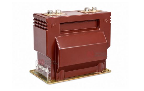
Product Display
6-12Q Epoxy Resin Cast Current Transformer Thomas Electric")
Main Applications
- 10kV, 11kV, and 12kV indoor medium-voltage distribution systems
- Air-insulated switchgear, metal-clad switchgear, feeder cabinets, and circuit breaker panels
- Current measurement and electric energy metering circuits
- Relay protection circuits with 5P or 10P protection accuracy requirements
- Industrial substations, utility distribution rooms, and commercial power distribution systems
- Power monitoring, SCADA, and energy management systems requiring isolated secondary current signals
Key Technical Features
- IEC 12kV insulation coordination: Suitable for 10kV, 11kV, and 12kV systems with rated insulation level of 12/42/75kV.
- Indoor epoxy resin casting: The primary winding, secondary winding, and core are molded into a fully enclosed cast-resin body for insulation strength and moisture resistance.
- Measurement and protection design: Supports metering classes such as 0.2S / 0.5S and protection classes such as 5P15, 10P10, or 10P15 according to project requirements.
- 1A or 5A secondary output: Suitable for connection to meters, protection relays, monitoring instruments, and switchgear secondary circuits.
- Short-circuit withstand capability: Short-time thermal current and dynamic current values are selected according to current ratio and system fault level.
- Fully enclosed support structure: The compact resin body supports indoor cabinet mounting and simplifies surface cleaning and maintenance.
- Standard and customized ratios: Standard current ratios are available, and special primary ratios, secondary currents, burdens, or terminal arrangements can be customized by technical agreement.
Working Principle
The LZZQB6-10 / LZZQB6-12 / LZZB(J)6-12Q / LZZBJ6-12 current transformer operates according to electromagnetic induction. The primary current generates magnetic flux in the core, and the secondary winding outputs a proportional current signal to meters, relays, or monitoring devices. The epoxy resin casting body provides electrical insulation between the medium-voltage primary circuit and the low-voltage secondary circuit.
For metering circuits, the transformer should maintain ratio accuracy and phase displacement within the rated burden. For protection circuits, the protection winding should provide a reliable secondary current signal under fault conditions and coordinate with the relay setting, accuracy limit factor, and system short-circuit withstand level.
Model Designation
6-12Q Epoxy Resin Cast Current Transformer Thomas Electric")
The model code identifies the product type, installation structure, insulation method, protection function, design sequence, and voltage class. The following explanation is used for the LZZQB6-12 and related 12kV Q-series current transformers.
| Code | Meaning |
|---|---|
| L | Current transformer |
| Z | Support type / post-type structure |
| Z | Cast-resin insulated / fully enclosed structure |
| Q | Enhanced structure or Q-series design platform |
| B | With protection function / protection-class configuration available |
| J | Reinforced or extended-rated secondary load design according to model configuration |
| 6 | Design sequence |
| 10 / 12 | Voltage class identification. LZZQB6-10 is used for 10kV-class projects, while LZZQB6-12 / LZZB(J)6-12Q / LZZBJ6-12 are used for 12kV-class insulation coordination and can cover 10kV, 11kV, and 12kV applications according to project requirements. |
Model variants: LZZQB6-12, LZZB(J)6-12Q, and LZZBJ6-12 are used for indoor epoxy resin cast current transformer applications. The final model shall be confirmed according to voltage class, current ratio, accuracy class, rated burden, mounting layout, and project drawing.
Technical Data
| Item | Specification |
|---|---|
| Rated voltage class | 10kV / 11kV / 12kV medium-voltage systems |
| Highest voltage for equipment | 12kV |
| Rated insulation level | 12/42/75kV |
| Rated frequency | 50Hz / 60Hz |
| Rated primary current | 20A to 1500A reference range; higher or customized ratios available according to project requirement |
| Rated secondary current | 5A or 1A |
| Accuracy class | 0.2S, 0.5S, 0.2, 0.5, 5P15, 10P10, 10P15 or project-specific combinations |
| Rated output | 10VA / 15VA / 20VA / 30VA / 40VA according to metering or protection core configuration |
| Metering security factor | FS 5 or FS 10 according to metering core requirement |
| Protection accuracy limit factor | 5P15 / 10P10 / 10P15 or project-specific ALF configuration |
| Ambient temperature | -5°C to +40°C |
| Insulation medium | Epoxy resin casting insulation |
| Installation type | Indoor support-type / penetration-type switchgear installation according to model structure |
| Applicable standard | IEC 61869-1 / IEC 61869-2; IEC 60044-1 can be referenced for legacy specification |
Windings & Terminal Marking

- Primary terminals: P1 / P2
- Secondary terminals (Group 1): 1S1 / 1S2
- Secondary terminals (Group 2): 2S1 / 2S2
The LZZQB6-10 / LZZQB6-12 / LZZB(J)6-12Q / LZZBJ6-12 current transformer can be supplied with metering, measurement, protection, or combined secondary winding configurations. The final terminal arrangement depends on the number of secondary cores and the approved wiring diagram.
| Terminal Marking | Function | Application Note |
|---|---|---|
| P1 / P2 | Primary terminals | The reference primary current direction is normally defined from P1 to P2. |
| 1S1 / 1S2 | First secondary winding | Usually used for metering, measurement, or the first specified secondary core. |
| 2S1 / 2S2 | Second secondary winding | Usually used for relay protection or an additional secondary circuit when required. |
| Secondary terminal cover | Secondary wiring protection | The protective terminal cover helps reduce accidental contact and supports safer wiring maintenance. |
Terminal markings follow standard CT polarity conventions. Correct terminal identification shall be observed to ensure metering accuracy, relay direction judgment, and protection performance. The secondary circuit must not be open-circuited when the primary circuit is energized.
Rated Current, Accuracy and Short-Circuit Withstand Reference
| Rated
Primary Current (A) |
Accuracy
Class Combination |
Metering
Output 0.2S / 0.5S (VA) |
Metering
Output 0.5 (VA) |
Protection
Output 5P15 / 10P15 (VA) |
Short-Time
Thermal Current |
Rated
Dynamic Current |
Weight
Reference |
|---|---|---|---|---|---|---|---|
| 20–100 | 0.2S / 0.5S 0.2S / 10P 0.5S / 10P |
10 | 15 | 15 | 150 × I1n | 375 × I1n | Approx. 28kg |
| 150–300 | 15 | 20 | 31.5kA | 80kA | |||
| 400 | 20 | 30 | 31.5kA | 80kA | |||
| 500–600 | 20 | 30 | 44.5kA | 80kA | |||
| 800 | 30 | 40 | 63kA | 100kA | |||
| 1000–1500 | 30 | 40 | 63kA | 100kA |
Note: The table is for preliminary engineering selection. If the secondary current is 1A or if the required parameters are beyond the listed range, the final current ratio, accuracy class, rated output, thermal current, dynamic current, and terminal arrangement shall be confirmed by technical agreement.
ALF vs Burden
The protection accuracy limit factor (ALF) varies with secondary burden. The curve illustrates the trend of protection accuracy capability under different burden conditions. Acceptance shall be based on nameplate data and test reports.

10P Accuracy Limit Factor and Burden Reference
| Rated Primary
Current (A) |
Typical
Protection Class |
Rated
Output (VA) |
Application
Note |
|---|---|---|---|
| 30–75 | 0.2 / 10P, 0.5 / 10P | 10 / 15 or 15 / 20 | Low-current feeder protection and metering circuits |
| 100–300 | 0.5 / 10P15 | 15 / 20 | Standard feeder metering and protection configuration |
| 400–600 | 0.2 / 0.5 / 10P15 | 20 / 20 / 30 or 30 / 30 | Medium-current switchgear protection applications |
| 800–3150 | 0.5 / 10P15 | 30 / 30 or 40 / 40 | High-current feeder and main incoming panel applications |
The 10P accuracy limit factor depends on the connected burden. Protection class and secondary burden must be verified against relay requirements and CT excitation characteristics.
Service Conditions
- Installation location: indoor medium-voltage switchgear
- System voltage: 10kV, 11kV, or 12kV class
- Rated frequency: 50Hz / 60Hz
- Rated insulation level: 12/42/75kV
- Ambient temperature: -5°C to +40°C
- Altitude: not exceeding 1000m under standard service conditions unless otherwise specified
- The installation environment should be free from severe vibration, corrosive gas, explosive medium, heavy pollution, and abnormal condensation.
- For high altitude, high humidity, coastal, heavy-pollution, or special switchgear applications, technical confirmation is recommended before ordering.
Standards & Compliance
The LZZQB6-10 / LZZQB6-12 / LZZB(J)6-12Q / LZZBJ6-12 current transformer can be supplied according to IEC 61869-1 and IEC 61869-2. IEC 60044-1 may be referenced for legacy project specifications. Routine tests, dielectric tests, polarity verification, ratio test, accuracy test, insulation resistance, and partial discharge requirements should be confirmed according to the final technical agreement.
Installation & Dimensions
6-12Q Epoxy Resin Cast Current Transformer Thomas Electric")
The LZZQB6-10 / LZZQB6-12 series is designed for indoor switchgear installation. The cast-resin body, base plate, mounting holes, primary terminal position, and secondary terminal cover shall be confirmed according to the approved outline drawing before switchgear design or batch production.
Structure & Overall
| Item | Selection Note |
|---|---|
| Mechanical structure | Indoor epoxy resin cast fully enclosed support-type structure |
| Primary terminals | P1 / P2 terminal plates according to approved drawing |
| Secondary terminals | Terminal block with protective cover according to secondary core configuration |
| Mounting base | Base plate with mounting holes for switchgear installation |
| Drawing confirmation | Final outline, terminal direction, and mounting dimensions shall be confirmed before switchgear production |
Installation & Safety Notes
- Confirm the model, voltage class, current ratio, secondary current, accuracy class, burden, insulation level, and short-circuit withstand requirement before installation.
- Check switchgear mounting space, primary terminal connection, phase clearance, grounding arrangement, and maintenance access against the approved drawing.
- Connect primary and secondary terminals according to the terminal markings and project wiring diagram.
- The secondary circuit of a current transformer must not be left open when the primary circuit is energized.
- During meter or relay maintenance, short-circuit the CT secondary circuit before disconnecting any secondary wiring.
- Secondary grounding shall follow the project specification and local electrical safety requirements.
- Installation and maintenance shall be performed by qualified medium-voltage electrical personnel.
Ordering Information
Please provide the following information when ordering or requesting a quotation:
- Product model: LZZQB6-12, LZZB(J)6-12Q, or LZZBJ6-12
- System voltage: 10kV, 11kV, or 12kV
- Rated primary current / current transformation ratio
- Rated secondary current: 1A or 5A
- Accuracy class combination and rated output for each secondary core
- Protection class and accuracy limit factor requirement
- Short-circuit withstand requirement: short-time thermal current and dynamic current
- Insulation level and applicable IEC standard
- Switchgear type, installation layout, terminal direction, and required outline drawing
- Quantity, labeling, certificates, routine test reports, and packaging requirements
- Special customized current ratio, secondary winding, or terminal arrangement requirements
Selection Guidelines
- Confirm system voltage: Select this CT for indoor 10kV, 11kV, or 12kV switchgear with 12kV-class insulation coordination.
- Confirm model variant: Choose LZZQB6-12, LZZB(J)6-12Q, or LZZBJ6-12 according to switchgear structure, protection requirement, and drawing configuration.
- Confirm current ratio: Select the primary current according to feeder load, continuous operating current, and relay protection setting range.
- Confirm secondary current: Use 5A or 1A according to metering instruments, protection relays, cable length, and total burden calculation.
- Define accuracy combination: Specify metering accuracy, protection class, rated output, FS, and ALF for each secondary winding.
- Verify short-circuit withstand: Check that short-time thermal current and rated dynamic current meet the switchgear fault-current level.
- Confirm customization: For 1A secondary current, non-standard ratios, special burdens, or terminal requirements, confirm by technical agreement before production.
FAQs