Product Overview
Functional Definition
The BH-0.66R (RCT) series current transformers are electromagnetic measuring instruments designed for accurate current measurement, electric energy metering, and relay protection applications in low-voltage AC power systems. These transformers utilize electromagnetic induction principles to provide galvanically isolated secondary current signals proportional to primary current.
Key Ratings Snapshot
| Item | Specification (per order / nameplate) |
|---|---|
| System voltage class | 0.66 kV or below (indoor low-voltage distribution applications) |
| Rated frequency | 50 Hz or 60 Hz |
| Rated secondary current | 5 A |
| Accuracy classes | 0.5, 1.0 (metering and protection cores) |
| Rated burden | 5 VA, 10 VA, 15 VA, 25 VA (per core/winding as specified) |
| Burden power factor | cosφ = 0.8 (lagging) unless otherwise specified |
| Insulation level | 0.5 kV / 3 kV (rated insulation voltage / withstand test voltage) |
| Applicable standards | GB/T 20840.8-2007 (Instrument Transformers – Part 8: Electronic Current Transformers); JB/T 5356-2002 (General Technical Requirements for Low-Voltage Current Transformers) |
| Core aperture variants | φ35, φ58, φ90, φ110 (for different primary conductor sections) |
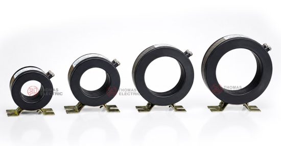
Product Shows

Working Principle
Operating on Faraday’s law of electromagnetic induction, the transformer features a loop-type (ring) magnetic core with the primary conductor (busbar or cable) passing through the aperture. The secondary winding is uniformly wound around the core. The magnetic flux generated by primary current induces proportional voltage in the secondary winding, delivering standardized output current (5 A) through the connected burden.
System Application Position
- Low-Voltage Distribution: 0.66 kV and below distribution panels and switchgear
- Energy Metering: Electric energy measurement and revenue metering systems
- Protection Circuits: Overcurrent and relay protection schemes in low-voltage systems
- Current Monitoring: Real-time current monitoring in industrial and commercial electrical installations
Structural Form Overview
Plastic-insulated construction with loop-type iron core design. The bottom-mounted installation configuration provides compact integration in low-voltage distribution equipment. The design includes a dedicated aperture for busbar passage and mounting plate for secure installation.
Model Designation

Model Code Explanation
- BH — Manufacturer designation (Duoma Electric)
- 0.66 — Rated voltage class (0.66 kV or below)
- R — Ring (loop-type) core configuration
- (RCT) — Product series designation: Resin-insulated Current Transformer for low-voltage applications
Service Conditions
The RCT series current transformers are designed for indoor operation under normal service conditions in low-voltage power systems.
- Installation environment: Indoor installation only
- Altitude: Not exceeding 1000 m above sea level
- Ambient temperature: −5 °C to +40 °C
- Relative humidity: ≤ 80%
- Environmental conditions: No serious atmospheric pollution; free from corrosive gases, explosive media, or severe mechanical vibration
Construction
Construction Design
- Core type: Loop-type (ring) iron core
- Insulation: Plastic insulated structure
- Winding: Secondary winding uniformly wound around the core
- Installation: Bottom-mounted with mounting plate and busbar aperture
Key Features
- Loop-Type Iron Core: Optimized magnetic flux path for efficient current transformation and accurate measurement over extended service periods
- Uniform Secondary Winding: Consistent winding distribution ensures accurate and reliable output for precision current measurement
- Mounting Plate for Secure Installation: Bottom-mounted design with mounting plate ensures stable operation within distribution systems
- Busbar Access Aperture: Dedicated aperture for primary conductor (busbar) passage facilitates straightforward electrical system integration
Windings & Terminal Marking
- Primary conductor: Busbar or cable passing through core aperture (no fixed terminals)
- Secondary terminals: Output terminals for secondary circuit connection
Terminal markings follow standard CT polarity conventions. Correct terminal identification shall be observed to ensure accurate metering and protection performance.
Technical Data
This section provides selection-oriented technical data for the RCT series indoor, plastic-insulated current transformer used in 0.66 kV class AC systems (50 Hz or 60 Hz). Data shown below is intended for preliminary selection of accuracy class, rated burdens, and transformation ratios.
Definitions: Rated transformation ratio indicates primary to secondary current ratio (e.g., 100/5). Rated output (VA) is specified per secondary core. Straight-through turn number indicates the number of primary conductor passes through the aperture (typically 1 for busbar applications).
Data Reference
| Type (Core Aperture) | Rated Transformation Ratio (A) | Busbar Section (mm) | Purchase Specification (mm) | Straight-through Turn Number | Accuracy Class and Rated Output (VA) cosφ = 0.8 |
Rated Insulation Level (kV) | |
|---|---|---|---|---|---|---|---|
| 0.5 | 1.0 | ||||||
| φ35 | 15/5 | — | — | 10 | 5 | 10 | 0.5/3 |
| 20/5 | — | — | 5 | 5 | 10 | ||
| 30/5 | — | — | 5 | 5 | 10 | ||
| 40/5 | — | — | 3 | 5 | 10 | ||
| 50/5 | — | — | 2 | 5 | 10 | ||
| 75/5 | — | — | 2 | 5 | 10 | ||
| 100/5 | 30 × 10 | 1 | 1 | 5 | 10 | ||
| φ58 | 150/5 | 30 × 10 | 1 | 1 | 10 | 15 | 0.5/3 |
| 200/5 | 30 × 10 | 1 | 1 | 10 | 15 | ||
| 300/5 | 50 × 10 | 1 | 1 | 10 | 15 | ||
| 400/5 | 50 × 10 | 1 | 1 | 10 | 15 | ||
| φ90 | 500/5 | 50 × 10 | 60 × 10 | 1 | 15 | 25 | 0.5/3 |
| 600/5 | 50 × 10 | 60 × 10 | 1 | 15 | 25 | ||
| 800/5 | 80 × 10 | 60 × 10 | 1-2 | 15 | 25 | ||
| 1000/5 | 80 × 10 | 60 × 10 | 1-2 | 15 | 25 | ||
| φ110 | 1200/5 | 80 × 10 | 80 × 10 | 1-2 | 15 | 25 | 0.5/3 |
| 1500/5 | 100 × 10 | 80 × 10 | 1-2 | 15 | 25 | ||
| 2000/5 | 100 × 10 | 80 × 10 | 1-2 | 15 | 25 | ||
| 2500/5 | 100 × 10 | 80 × 10 | 1-2 | 15 | 25 | ||
| 3000/5 | 100 × 10 | 80 × 10 | 1-2 | 15 | 25 | ||
| 4000/5 | 100 × 10 | 80 × 10 | 1-2 | 15 | 25 | ||
Standards & Normative References
| Standard | Title | Application |
|---|---|---|
| GB/T 20840.8-2007 | Instrument Transformers – Part 8: Electronic Current Transformers | National standard for low-voltage current transformers |
| JB/T 5356-2002 | General Technical Requirements for Low-Voltage Current Transformers | Industry standard for low-voltage CT technical requirements |
| GB/T 13384-2008 | General Requirements for Electrical Equipment | General electrical equipment requirements |
Factory Testing Compliance
- Routine tests per applicable GB requirements (including polarity verification, ratio verification, and accuracy verification per specified class and burden)
- Dielectric tests per insulation coordination requirements
- Visual and dimensional inspection including marking and workmanship conformity
- Type tests as required by the project specification
Installation & Dimensions

- Outline dimensions and mounting details are provided in the dimensional drawings below
- The transformer shall be securely mounted using the designated fixing holes on the mounting plate
- Primary conductor connection is made by passing busbar or cable through the core aperture
- Adequate clearance shall be maintained for insulation integrity and maintenance access
Outline and Dimensions
| Type | d (mm) | A (mm) | B (mm) | D (mm) | G (mm) | H (mm) | L (mm) |
|---|---|---|---|---|---|---|---|
| RCT-35 | 35 | 95 | 80 | 78 | 45 | 90 | 54 |
| RCT-58 | 58 | 110 | 88 | 100 | 45 | 113 | 56 |
| RCT-90 | 90 | 110 | 88 | 135 | 38 | 147 | 40 |
| RCT-110 | 110 | 110 | 88 | 163 | 38 | 177 | 40 |
Safety Notes
- Secondary circuit must never be left open when the transformer is energized, as dangerous high voltage may appear across the secondary terminals
- During inspection or maintenance, the secondary circuit shall be short-circuited before disconnecting any instruments
- One point of the secondary circuit should be reliably grounded in accordance with applicable standards
- All installation and maintenance work shall comply with local electrical safety regulations
Ordering Information
When placing an order, the required configuration shall be specified according to the local electrical requirements, applicable standards, and project technical specification. The following parameters shall be clearly stated for technical confirmation and production release:
- Rated primary current / transformation ratio (e.g., 100/5, 200/5)
- Rated secondary current (5 A standard)
- Accuracy class (0.5 or 1.0 for metering and/or protection applications)
- Rated burden (VA) for secondary circuit
- Core aperture size (φ35, φ58, φ90, or φ110 based on primary conductor section)
How to Select:
- Determine rated primary current (Ip) based on circuit load rating and expected operating range
- Select accuracy class (0.5 for metering; 1.0 for protection or general measurement)
- Confirm rated burden (VA) based on connected meters/relays and wiring losses
- Verify core aperture size accommodates primary conductor (busbar or cable) section
If local utility or project requirements apply (e.g., specific insulation level, terminal arrangement, mounting constraints, documentation language, or required certificates), specify them at the ordering stage. Special configurations shall be confirmed by technical agreement prior to production.
FAQs
Q1: What are the primary applications of the RCT Indoor Current Transformer?
A: The RCT is used for accurate current measurement, energy metering, and relay protection in low-voltage electrical systems with rated voltage of 0.66 kV or below.
Q2: Can the RCT transformer be used in outdoor environments?
A: No, the RCT transformer is specifically designed for indoor use only. Outdoor applications require transformers with appropriate environmental protection ratings.
Q3: What is the maximum rated voltage for the RCT transformer?
A: The RCT transformer is designed for use in systems with a rated voltage of 0.66 kV or below.
Q4: How to select the appropriate core aperture size?
A: Core aperture size (φ35, φ58, φ90, or φ110) shall be selected based on the primary conductor (busbar or cable) cross-sectional dimensions to ensure adequate clearance for installation.
Q5: What accuracy classes are available for the RCT transformer?
A: The RCT transformer is available in accuracy class 0.5 (for precision metering) and 1.0 (for protection and general measurement applications).
Q6: Is the RCT transformer customizable?
A: Yes, the RCT transformer can be customized with different current ratios, accuracy classes, and rated burdens to suit specific operational requirements.
Q7: What are the mandatory secondary handling requirements?
A: Do not open-circuit CT secondary under energized primary. Short-circuit and ground the secondary per project practice. Observe correct terminal polarity for accurate metering and protection.