Product Overview
Functional Definition
The SDH-0.66, BH-0.66(IV)(V) series current transformers are precision electromagnetic instruments designed for accurate current measurement and energy metering in low-voltage AC power systems (0.66 kV class). These transformers utilize electromagnetic induction principles to provide galvanically isolated secondary current signals proportional to primary current, specifically engineered for indoor distribution panels, switchgear cabinets, and metering applications.
Key Ratings Snapshot
| Item | Specification (per order / nameplate) |
|---|---|
| System voltage class | 0.66 kV (660V class, low-voltage distribution) |
| Rated frequency | 50 Hz (standard) |
| Rated secondary current | 1 A or 5 A |
| Accuracy classes | Metering cores: 0.2, 0.2s, 0.5, 0.5s |
| Rated burden | 5 VA or 10 VA (per core/winding as specified) |
| Burden power factor | cosφ = 0.8 (lagging) unless otherwise specified |
| Window aperture sizes | Series IV: 60×30, 80×30, 100×30, 120×50 mm Series V: 60×30, 80×30, 100×50, 120×50, 130×50 mm |
| Insulation level | Per GB1208-2006 and IEC60044-1:2003 |
| Applicable standards | GB1208-2006; IEC60044-1:2003; manufacturer-specific requirements |
| Series variants | BH-0.66(IV) / BH0.66(V) |
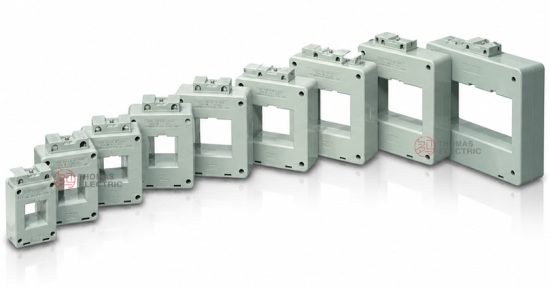
Product Shows
 Low-Voltage Indoor CT Thomas Electric")
Images showing SDH-0.66 BH-0.66(IV) series with multiple window size variants and SDH-BH0.66(V) series configurations
Working Principle
Operating on Faraday’s law of electromagnetic induction, the transformer features a toroidal magnetic core with primary conductor (busbar or cable) passing through the rectangular aperture and secondary windings wound around the core. The magnetic flux generated by primary current induces proportional voltage in the secondary winding, delivering standardized output current (1A or 5A) through connected burden (meters or relays).
System Application Position
- Low Voltage Distribution: 0.66kV (660V) distribution panels and switchgear
- Energy Metering: Electricity consumption measurement in industrial and commercial installations
- Load Monitoring: Current monitoring for motors, transformers, and distribution feeders
- Building Management Systems: Integration with power monitoring and energy management systems
Structural Form Overview
Indoor plastic case construction with fully-enclosed design ensures adequate insulation performance, moisture resistance, and mechanical durability for low-voltage applications. The rectangular window (square hole) mounting configuration accommodates busbar or cable feedthrough while maintaining compact installation footprint in distribution cabinets and metering panels.
Model Designation
 Low-Voltage Indoor CT Thomas Electric")
Model Code Explanation
- BH — Product series designation (indoor plastic case type)
- 0.66 — Voltage class: 0.66 kV (660V)
- (IV) or (V) — Design series variant
- Window dimensions — Rectangular aperture size in millimeters (e.g., 60×30, 80×30, 100×30, etc.)
Variant Differences
SDH-BH-0.66(IV) and SDH-BH0.66(V) series are electrically equivalent when specified with the same ratio, accuracy classes, and burdens. The differences between IV/V variants are primarily mechanical dimensions and window size availability to accommodate different busbar cross-sections and installation constraints in low-voltage switchgear.
Service Conditions
The BH-0.66 series current transformers are designed for indoor operation under normal service conditions in low-voltage power distribution systems.
- Installation environment: Indoor installation only (enclosed distribution cabinets or switchgear)
- Altitude: Not exceeding 1000 m above sea level (higher altitude requires engineering confirmation)
- Ambient temperature: −5 °C to +40 °C
- Relative humidity: Daily average ≤ 95%, monthly average ≤ 90%
- Environmental conditions: Free from corrosive gases, explosive atmospheres, severe vibration, or mechanical shock
Construction
Construction Design
- Structure: Indoor plastic case, window-type (square hole / rectangular aperture)
- Insulation: Fully enclosed plastic insulation suitable for 660V systems
- Core: Ring-type magnetic core design
- System: Integrated primary and secondary insulation system
The plastic case construction provides adequate insulation properties and resistance to moisture and contamination for long-term indoor service in low-voltage distribution environments.
Windings & Terminal Marking
- Primary circuit: Busbar or cable passes through rectangular window aperture
- Secondary terminals: Marked according to polarity conventions (typical: S1 / S2 or K / L)
Terminal markings follow standard CT polarity conventions. Correct terminal identification shall be observed to ensure metering accuracy and proper connection to meters or monitoring equipment.
Technical Data
This section provides selection-oriented technical data for the BH-0.66 (IV/V) series indoor, plastic case current transformer used in 0.66 kV (660V) class AC systems (50 Hz). Data shown below is intended for preliminary selection of accuracy class combinations, rated burdens, and window aperture dimensions.
Definitions: Accuracy class combination indicates available metering cores in one CT. Rated output (VA) is specified per secondary core. Window dimensions determine busbar accommodation.
Notation: User’s data may extend beyond the standard ratings listed. Special configurations shall be confirmed by technical agreement and manufacturer validation prior to production.
Data Reference — BH-0.66(IV) Series
| Rated Primary Current (A) | Rated Secondary Current (A) | Accuracy Class | Rated Output (VA) |
|---|---|---|---|
| 600, 800, 1000, 1500 | 5 | 0.2 | 5 |
| 5, 1 | 0.2s | — | |
| 2000, 3000 | 1 | 0.5 | |
| — | 0.5s | 10 |
Data Reference — BH0.66(V) Series
| Rated Primary Current (A) | Rated Secondary Current (A) | Accuracy Class | Rated Output (VA) |
|---|---|---|---|
| 600, 800, 1000, 1500 | 5 | 0.2 | 5 |
| 5, 1 | 0.2s | — | |
| 2000, 3000 | 1 | 0.5 | |
| — | 0.5s | 10 |
Standards & Normative References
| Standard | Title | Application |
|---|---|---|
| GB1208-2006 | Current Transformers | National standard for CT requirements |
| IEC60044-1:2003 | Instrument Transformers – Part 1: Current Transformers | International standard for CT requirements |
Factory Testing Compliance
- Routine tests per applicable GB/IEC requirements (including polarity/marking verification, ratio verification, accuracy verification per specified class and burden)
- Dielectric tests per insulation coordination requirements and applicable standard
- Visual and dimensional inspection including marking and workmanship conformity
- Type and special tests as required by project specification
Installation & Dimensions
 Low-Voltage Indoor CT Thomas Electric")
Installation Requirements
- The transformer shall be securely mounted using the designated mounting holes or brackets
- Primary conductor (busbar or cable) passes through the rectangular window aperture
- Window aperture size shall be selected to accommodate the busbar cross-section with adequate clearance
- Adequate space shall be maintained for secondary terminal access and wiring
Dimensional Data — BH-0.66(IV) Series
| Model | a (mm) | b (mm) | h (mm) | A (mm) | B (mm) | H (mm) |
|---|---|---|---|---|---|---|
| BH0.66(IV)60×30 | 32 | 62 | 112 | 83.5 | 47 | 128 |
| BH0.66(IV)80×30 | 32 | 83 | 134 | 93.5 | 48 | 150 |
| BH0.66(IV)100×30 | 32 | 102 | 154 | 99 | 48 | 170 |
| BH0.66(IV)120×50 | 52 | 124 | 203 | 134 | 64.5 | 219 |
Dimensional Data — BH0.66(V) Series
| Model | a (mm) | b (mm) | h (mm) | A (mm) | B1 (mm) | B2 (mm) | H (mm) |
|---|---|---|---|---|---|---|---|
| BH0.66(V)60×30 | 33 | 62 | 125 | 100 | 56 | 73 | 141 |
| BH0.66(V)80×30 | 33 | 83 | 149.5 | 100 | 56 | 73 | 165.5 |
| BH0.66(V)100×50 | 54 | 103 | 175 | 124 | 56 | 73 | 191 |
| BH0.66(V)120×50 | 54 | 122 | 198 | 124 | 56 | 73 | 214 |
| BH0.66(V)130×50 | 55 | 132 | 204 | 130 | 56 | 73 | 220 |
Note: Dimensions a, b represent internal window aperture size; A, B, H represent overall external dimensions. Refer to dimensional drawings for complete mounting details.
Safety Notes
- Secondary circuit must never be left open when the transformer is energized, as dangerous high voltage may appear across the secondary terminals
- During inspection or maintenance, the secondary circuit shall be short-circuited before disconnecting any instruments
- One point of the secondary circuit should be reliably grounded in accordance with applicable standards
- All installation and maintenance work shall comply with local electrical safety regulations for low-voltage equipment
Ordering Information
When placing an order, the required configuration shall be specified according to the installation requirements, applicable standards, and project technical specification. The following parameters shall be clearly stated for technical confirmation and production release:
- Rated primary current / transformation ratio (e.g., 1000/5A, 1500/1A)
- Rated secondary current (1 A or 5 A)
- Accuracy requirements (metering accuracy class: 0.2, 0.2s, 0.5, 0.5s)
- Rated burden (VA) for secondary core/winding
- Window aperture size (select from available dimensions per series)
- Series variant (BH-0.66(IV) or BH0.66(V))
How to select
1: Determine rated primary current (Ip) based on feeder/load rating and expected operating range in the 660V distribution system.
2: Select metering accuracy requirements (e.g., 0.2 or 0.2s for revenue metering; 0.5 or 0.5s for monitoring).
3: Confirm rated burden (VA) based on connected meters and wiring losses.
4: Select window aperture size to accommodate busbar cross-section with adequate clearance.
If local utility or project requirements apply (e.g., specific insulation level, terminal arrangement, mounting constraints, documentation language, or required certificates), specify them at the ordering stage. Special configurations shall be confirmed by technical agreement and final data sheet prior to production.
FAQs
Q1: How to select CT ratio and rated primary current for a 0.66kV indoor current transformer?
A: Select CT ratio / rated primary current (Ip) from feeder continuous load current and required measurement range, then verify against the 660V distribution system design and metering equipment requirements.
Q2: How are metering accuracy classes specified (GB1208-2006 / IEC60044-1)?
A: Specify metering accuracy class (0.2, 0.2s, 0.5, 0.5s) and rated burden (VA) per GB1208-2006 and IEC60044-1:2003 requirements based on metering application (revenue-grade or monitoring).
Q3: How to determine rated burden (VA) for 1A/5A CT secondary circuits?
A: Rated burden (VA) shall cover total connected load (meter + relay + wiring loss) for 1A or 5A secondary current and shall be confirmed during engineering design.
Q4: How to select window aperture size for busbar installation?
A: Window aperture size (e.g., 60×30, 80×30, 100×50 mm) shall be selected to accommodate the busbar cross-section with adequate clearance for installation and thermal expansion.
Q5: Are BH-0.66(IV) and BH0.66(V) series electrically interchangeable?
A: Yes. With identical ratio/accuracy/burden specifications, IV and V series are electrically equivalent; selection is based on window size availability and mounting configuration.
Q6: What are mandatory secondary handling and polarity requirements?
A: Do not open-circuit CT secondary under energized primary. Short and ground per project practice; observe terminal polarity markings for correct meter connection.
Q7: Which documents govern compliance (GB/IEC standards, traceability)?
A: Nameplate and factory test report prevail. Compliance follows GB1208-2006 and IEC60044-1:2003; unit test certificates are traceable to accredited laboratories.