Product Overview
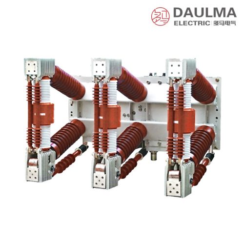
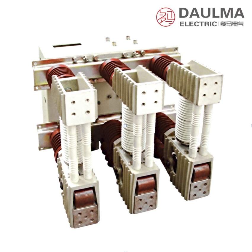
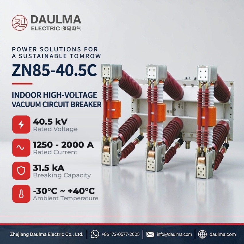
The ZN12 is a three-phase 50 Hz withdrawable handcart indoor vacuum circuit breaker, offered as ZN12-12 (12 kV) and ZN12-40.5G (40.5 kV). The 40.5 kV version covers currents of 1250-2000 A with breaking of 25 or 31.5 kA, 4 s short-time rating and capacitor breaking of 630 A single / 400 A back-to-back, in compact fully insulated poles for metal-enclosed switchgear.
Product Display
Model Designation
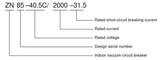
Technical type code: ZN85 − 40.5 C / □ − □ (marketed as ZN12-12 / ZN12-40.5G)
- Z — Vacuum circuit breaker
- N — Indoor installation
- 85 — Design sequence number
- 40.5 — Rated voltage (kV)
- C — Handcart (withdrawable) type
- First □ — Rated current (A)
- Second □ — Rated short-circuit breaking current (kA)
Example: ZN85-40.5C / 2000 − 31.5 identifies a 40.5 kV handcart vacuum circuit breaker of 2000 A rated current with 31.5 kA rated short-circuit breaking current.
Service Conditions
- Ambient temperature: −30 °C to +40 °C
- Altitude: not exceeding 2000 m (above 1000 m the rated insulation level is raised accordingly)
- Relative humidity: daily average ≤ 95%, monthly average ≤ 90%
- Seismic intensity: not exceeding degree 8
- Air free from corrosive gas vapour, chemical attack, violent vibration, fire and explosion hazard
- Service outside these limits: consult the manufacturer for evaluation
Construction
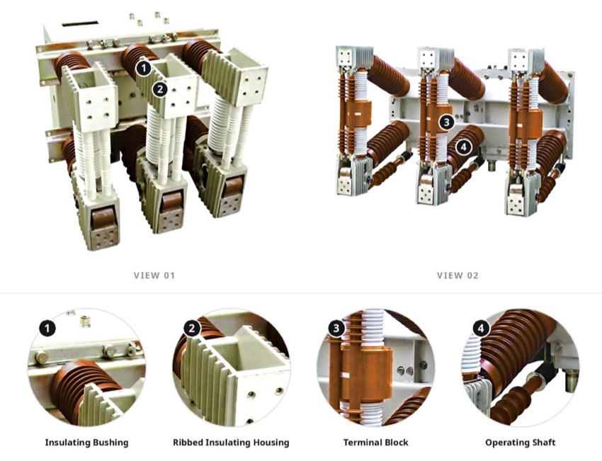
Each phase carries a sealed vacuum interrupter inside a fully enclosed, fully insulated pole assembly, giving a high insulation level of 185 kV impulse and 95 kV power frequency with no fire or explosion risk and no maintenance of the interrupting medium. The spring energy-storage mechanism closes from stored spring energy while the closing and opening coils are energised on command, the spring being charged from an AC or DC 110 / 220 V supply or by manual handle.
The breaker is assembled on a chassis as a withdrawable unit that racks between the connected, test and disconnected positions of metal-enclosed switchgear, allowing isolation or removal while the cubicle remains energised. Primary current transfers through the chassis static contacts, secondary circuits reach the control, protection and measurement loops via the terminal block, and mechanical interlocks together with reliable earthing of frame and switchgear body protect operation and maintenance.
Technical Data
| No. | Item | Unit | Data |
|---|---|---|---|
| 1 | Rated Voltage | kV | 40.5 |
| 2 | Rated Frequency | Hz | 50 |
| 3 | Rated Current | A | 1250 1600 2000 |
| 4 | Rated Short-Circuit Breaking Current | kA | 25 31.5 |
| 5 | Rated Short-Time Withstand Current | kA | 25 31.5 |
| 6 | Rated Short-Circuit Duration | s | 4 |
| 7 | Rated Peak Withstand Current | kA | 63 80 |
| 8 | Rated Short-Circuit Making Current (peak) | kA | 63 80 |
| 9 | Rated Lightning Impulse Withstand Voltage (peak) | kV | 185 |
| 10 | 1 min Power-Frequency Withstand Voltage | kV | 95 |
| 11 | Rated Short-Circuit Breaking Time | ms | < 80 |
| 12 | Opening Time | ms | 50 |
| 13 | Closing Time | ms | ≤ 80 |
| 14 | Rated Operating Sequence | — | O – 0.3 s – CO – 180 s – CO |
| 15 | Breaking Operations at Rated Short-Circuit Current | times | 20 |
| 16 | Rated Single Capacitor Bank Breaking Current | A | 630 |
| 17 | Back-to-Back Capacitor Bank Breaking Current | A | 400 |
| 18 | Mechanical Life | operations | 10000 |
| 19 | Rated Operating Voltage (AC/DC) | V | 110 220 |
Standards
The breaker is designed and type-tested to GB/T 1984 for AC high-voltage circuit breakers and to IEC 62271-100, with manufacturing and inspection carried out according to DL/T 403 for indoor high-voltage vacuum circuit breakers of 3.6 kV to 40.5 kV.
Installation & Dimensions
Installation Diagram
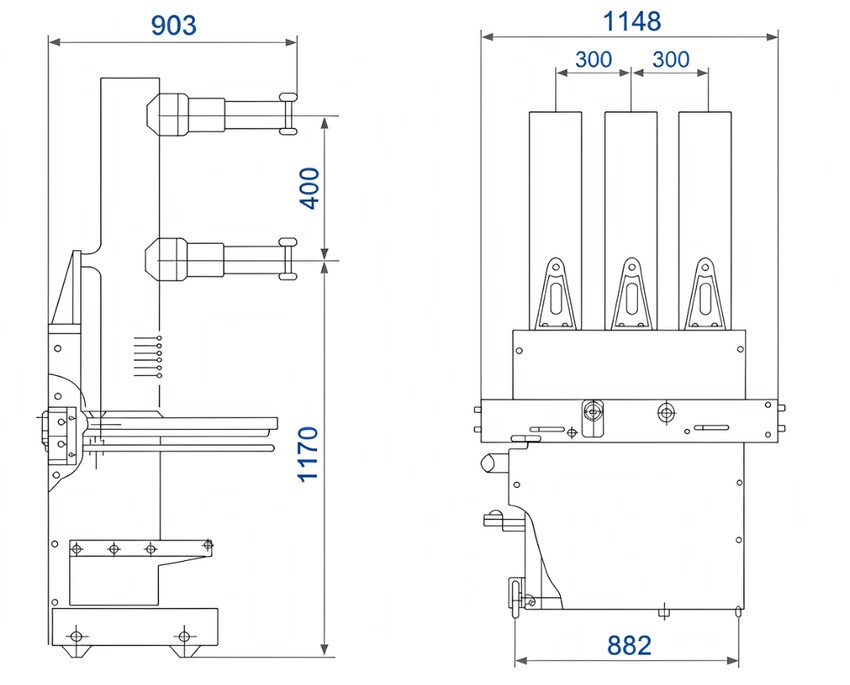
The unit is supplied as a withdrawable handcart breaker on a chassis that racks between the connected, test and disconnected positions, so it can be isolated or withdrawn without de-energising the cubicle. Before commissioning, verify the interlocks, confirm nameplate ratings against the panel duty and earth the breaker frame and switchgear body reliably.
| Outline Dimension | View | Value (mm) |
|---|---|---|
| Overall Width | Front | 1148 |
| Pole (phase) Spacing | Front | 300 + 300 |
| Base / Wheelbase Width | Front | 882 |
| Overall Depth | Side | 903 |
| Upper Section Height | Side | 400 |
| Lower Section Height | Side | 1170 |