Product Overview
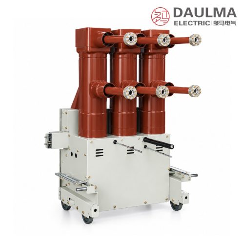
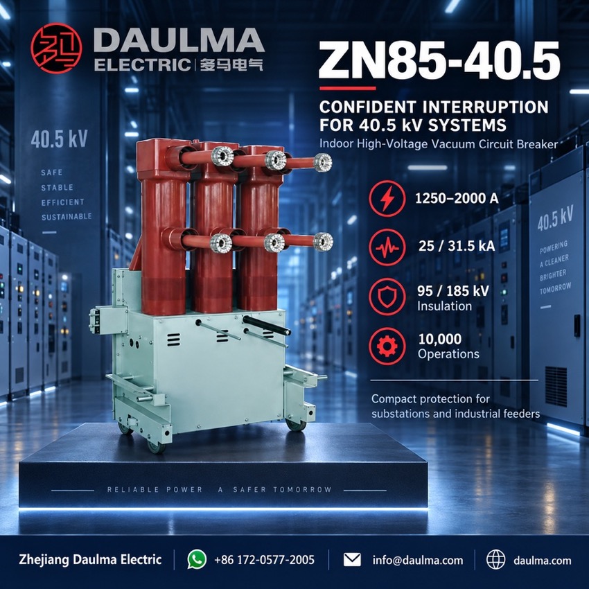
The ZN85-40.5 is a three-phase AC 50 Hz indoor high-voltage vacuum circuit breaker for 40.5 kV systems in power plants, substations and industrial networks, switching load, overload and fault currents. An upper-and-lower pole layout cuts installation depth, and the spring energy-storage mechanism is integrated in the frame as one compact unit with the moving and fixed parts.
Product Display
Model Designation
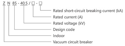
Type code: Z N 85 – 40.5 / □ – □
- Z — vacuum circuit breaker
- N — indoor type
- 85 — design sequence number
- 40.5 — rated voltage (kV)
- First □ — rated current (A)
- Second □ — rated short-circuit breaking current (kA)
Service Conditions
- Altitude: not exceeding 1000 m above sea level
- Ambient temperature: −25 °C to +40 °C
- Relative humidity: daily average ≤ 95%
- Surrounding air free from hazardous gases, explosive dust and severe vibration
Construction
A motor charges the closing spring; when the closing electromagnet is energised the stored energy closes the contacts and simultaneously preloads the opening spring and the contact pressure spring. Tripping the opening electromagnet releases the opening spring to separate the contacts inside the sealed vacuum interrupter, where the arc is extinguished without any external quenching medium.
Manual charging is performed by inserting the hand lever into the mechanism and working it through approximately 60 strokes. Once charged, the manual open and close buttons remain operative even if the control supply fails, so the breaker stays serviceable during auxiliary power loss.
Technical Data
| Item (Parameter) | Unit | Data |
|---|---|---|
| Rated Voltage | kV | 40.5 |
| Rated Current | A | 1250 1600 2000 |
| Rated Frequency | Hz | 50 |
| Rated Short-Circuit Breaking Current | kA | 25 31.5 |
| Rated Short-Circuit Making Current (Peak) | kA | 63 80 |
| 4 s Rated Short-Time Withstand Current | kA | 25 31.5 |
| Rated Peak Withstand Current | kA | 63 80 |
| 1-Minute Power Frequency Withstand Voltage | kV | 95 |
| Lightning Impulse Withstand Voltage (Peak) | kV | 185 |
| Rated Operating Sequence | — | O – 0.3 s – CO – 180 s – CO |
| Rated Short-Circuit Breaking Current Operations | times | 20 |
| Mechanical Life | times | 10000 |
| Opening Time | ms | ≤ 80 |
| Single Capacitor Bank Breaking Current | A | 630 |
| Back-to-Back Capacitor Bank Breaking Current | A | 400 |
| Rated Operating Voltage | V | DC 110 / AC 110 DC 220 / AC 220 |
Standards
The breaker is designed, manufactured and tested in accordance with the applicable IEC and GB standards for high-voltage AC circuit breakers and indoor high-voltage vacuum circuit breakers.
Installation & Dimensions
Installation Diagram
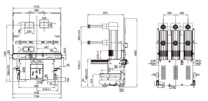
The compact upper-and-lower arrangement of poles and mechanism minimises the switchgear depth required by the panel. During installation leave adequate clearance for manual charging, cable termination and maintenance access, and verify earthing and interlock function before first energisation.
| Dimension | Value (mm) |
|---|---|
| Height | 2100 |
| Width | 1200 |
| Depth | 2800 |
| Mounting Hole Spacing (Vertical) | 630 |
| Mounting Hole Spacing (Horizontal) | 700 |
| Phase Spacing | 300 |